
-

SUBSCRIBE TO SHIPS IN SCALE TODAY!
The beloved Ships in Scale Magazine is back and charting a new course for 2026!
Discover new skills, new techniques, and new inspirations in every issue.
NOTE THAT OUR NEXT ISSUE WILL BE July/August 2026 -

Win a Free Custom Engraved Brass Coin!!!
As a way to introduce our brass coins to the community, we will raffle off a free coin during the month of August. Follow link ABOVE for instructions for entering.


You are using an out of date browser. It may not display this or other websites correctly.
You should upgrade or use an alternative browser.
You should upgrade or use an alternative browser.
USS Constitution - Model Shipways
- Thread starter Der Alte Rentner
- Start date
- Watchers 29




Ding, ding, ding!! Love the way your bell is mounted!The only constructive thing I managed to get done today was to actually mount the bell.



Before getting sidetracked in research for the acquisition or construction of a rope walking machine, I thought I'd at least try to rig one of the swifters. I don't even want to say how many hours I have invested in this little bit of rigging. Let me just say it was a very steep learning curve.
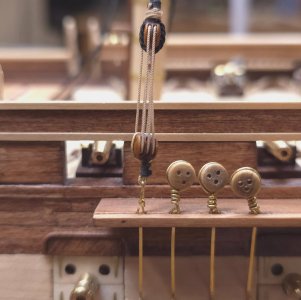
The 1.1mm rope doesn't look bad wrapped around the 4.8mm double block. The correctly sized block (4.0mm) looked ridiculous with this rope wrapped around it. Unfortunately this means I may need to invested in a few more 1/8" (4.8mm) in double blocks.
For the sake of symmetry, I will do the starboard side next. Then shift my attention to rope making.
The 1.1mm rope doesn't look bad wrapped around the 4.8mm double block. The correctly sized block (4.0mm) looked ridiculous with this rope wrapped around it. Unfortunately this means I may need to invested in a few more 1/8" (4.8mm) in double blocks.
For the sake of symmetry, I will do the starboard side next. Then shift my attention to rope making.

- Joined
- Oct 9, 2020
- Messages
- 2,666
- Points
- 538

looks good.
Looks good, Peter!


Ships of Scale is not consistent in their notifications. A week's worth interesting conversation took place here and I was not notified, so my reactions are a little dated.

I am surprised you had to fabricate your own bell. My 2016-7 MS kit provided me with one, but yours looks as good if not better than the kit's. Well done!While the mast was still off the boat, I thought it best to fit the ship's bell, which of course I need to fabricate.
That picture was taken between 1918 and 1920. It my belief that those windows were remanences of when the ship was a receiver ship and barracks. Back in 1898 till about 1906, it had a barn-like structure on and over the spar deck to house trainees. The structure was removed around 1906-7. Based on the photos, the windows were removed sometime in the 1940s or 50s.To pique my interest, he supplied this photo. It shocked me to learn that behind the closed gunport lids, there were windows!
To answer your question, that site was one of many I found photos and yes, I did have that photo.Jon, perhaps there are some pix here that even you don't already have, but somehow, I suspect you already know of this site.
Yes, the kit provided a Britannia bell.I am surprised you had to fabricate your own bell. My 2016-7 MS kit provided me with one, but yours looks as good if not better than the kit's.
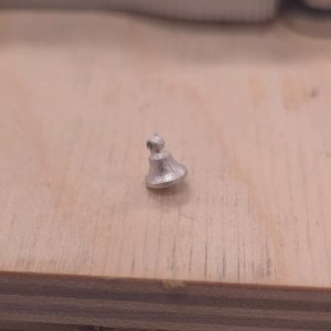
Given a choice between painting it and trying to make it look like brass, or turning one myself, I took the better looking option. I did have the Sherline lathe, after all..
- Joined
- Oct 9, 2020
- Messages
- 2,666
- Points
- 538
yeah i was looking at that kit "bell" the other day. I think I am going to try and buy one. what a piece of junk
Right tools for the right job!Yes, the kit provided a Britannia bell.
Given a choice between painting it and trying to make it look like brass, or turning one myself, I took the better looking option. I did have the Sherline lathe, after all..
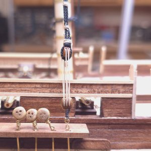
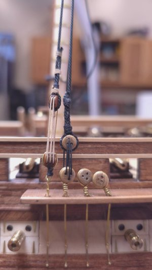
More fits and starts today as is befitting the early stages of the learning curve. But I've managed to add the starboard side Swifter and the first port side shroud.
It being Thursday and therefore Manhattan Club night, I headed over to my brothers.
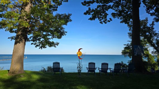
Evidently Landscaping has its challenges.
The Landscaping crew actually finished their job yesterday. But my brother asked the foreman if they could stay another day so we could see them before they left.
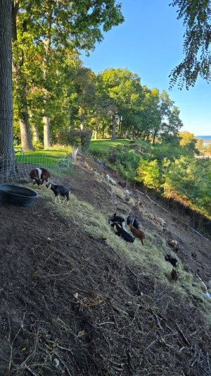
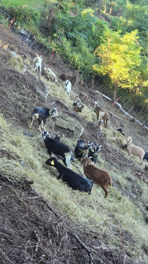
Evidently Landscaping has its challenges.
The Landscaping crew actually finished their job yesterday. But my brother asked the foreman if they could stay another day so we could see them before they left.
Deleted duplicate


Ah, the many challenges of Lake Michigan bluff living...It being Thursday and therefore Manhattan Club night, I headed over to my brothers.
View attachment 642168
Evidently Landscaping has its challenges.
The Landscaping crew actually finished their job yesterday. But my brother asked the foreman if they could stay another day so we could see them before they left.
View attachment 642169
View attachment 642170
- Joined
- Oct 9, 2020
- Messages
- 2,666
- Points
- 538
goat greenskapes inc
- Joined
- Oct 9, 2020
- Messages
- 2,666
- Points
- 538
my problem with the practicum is that he does not show enough overall pictures like of a completed mast, or yard, or the entire ship rigged.I got frustrated with the rigging research, and decided I'd shift gears to tackle the little that's left to do by way of fabrication - and that would be the crosstrees and trestle trees. (Hmmm, why is "crosstree" one word, and "trestle tree" two, at least in the MS plans?).
Yet again, I find myself disappointed by the MS plans and the Hunt Practicum.
First up, the MS plans: In order to make the 1st and 2nd (counting from bow to stern) crosstree components any of the cross tree sets, I had to figure out a way to determine their lengths. (The lengths of only the third branch(?) for each crosstree is provided. The 30 degree angle defining the ends of all three branches seemed to be the most likely avenue to explore for a solution. So, I fired up Corel Draw and did what I could to create the shape of the third branch of the main crosstree, and scaled everything from that (see below)
MS plans (note the presence of chocks on the 2nd and 3rd branches).
View attachment 632027
View attachment 631948
and note their absence here in Chapter 1 of Hunt's Rigging Practicum.
View attachment 631949
But wait, there's more... A reference in Chapter 5!
View attachment 631950
So, here's my first attempt to whip up scaled patterns from which to cut the crosstree components out of boxwood.
View attachment 631951
I could have simply used these patterns and started fabrication, but had to double check the dimensions for the openings for the masts.
Here's where I have a small problem. The MS plans show dimensions for the cross-sections of the masts, but there seems to be disagreement between the numbers. Look at the dimensions of the topmast at the shoulder where the crosstrees and cross trestle would sit.
F 5/32"
M 3/16"
Miz 1/8"
View attachment 632061
Compare that to any of these dimensions for the base of the topgallant mast.
View attachment 632062
I'm pretty sure I went on a rant about this a long time ago when I made the masts. There was a note in the addendum that came with the MS kit's inventory list with dimensions that supersede one of this group of three.
"Fore, main and mizzen Topgallant/royal masts Should read:
F - 3/16"
M - 1/4"
Miz - 1/8" "
Great, but I never knew which values these were replacing.
Judging by the actual measurements of the cross-sections at these two points, I went with those at the shoulder on the topmast. But now that I'm making the crosstrees, I see that the matching mast sections should be the same dimension, which is not the case. Fortunately, the difference for the main crosstree openings are only off by 1/32". Both openings should either be 3/16" or 5/32". I suppose I could add material to the 5/32" end of the topgallant mast to bring it to 3/16", but I can probably just live with a little bit of slack here. The other crosstree openings will pair with the same sized mast segments. Fore mast TS mast at shoulder is 5/32" square, as is the bottom of the topgallant mast. Ditto for the 1/8" square segments of the mizzen masts.
I revisited Corel Draw to prepare a more accurate rendering for the patterns, but wearying of the effort, I called it quits after demonstrating how I got the basic dimensions for the 1st and 2nd trees.
View attachment 632068
Construction will have to wait until Monday...
Have a nice weekend all.
I agree 100%.my problem with the practicum is that he does not show enough overall pictures like of a completed mast, or yard, or the entire ship rigged.
I can't remember who it was, but somebody at this site told me that the reason for that is that Bob never actually finished the model.
That was me. I have purchased two of his practicums (Rattlesnake & USS Constitution) and don't regret it. He didn't finish either of them. He does just enough to show his readers how to build their models. And if you follow his instructions, he covers a lot of the hard stuff on the hulls and you will get a decent model. But, a lot of detail stuff is omitted or simplified. Hence no pictures of the rigging as he didn't actual rig his model.I can't remember who it was, but somebody at this site told me that the reason for that is that Bob never actually finished the model.
Jon