


- Joined
- Dec 7, 2022
- Messages
- 230
- Points
- 113

I find it very convenient for a lot of work - more so than getting out the 'big' Dremel!Good to see someone else using the Dremel Stylo.
One of my favorite and most used tools.

 |
The beloved Ships in Scale Magazine is back and charting a new course for 2026! Discover new skills, new techniques, and new inspirations in every issue. NOTE THAT OUR NEXT ISSUE WILL BE July/August 2026 |
|
 |
As a way to introduce our brass coins to the community, we will raffle off a free coin during the month of August. Follow link ABOVE for instructions for entering. |
|
I find it very convenient for a lot of work - more so than getting out the 'big' Dremel!Good to see someone else using the Dremel Stylo.
One of my favorite and most used tools.


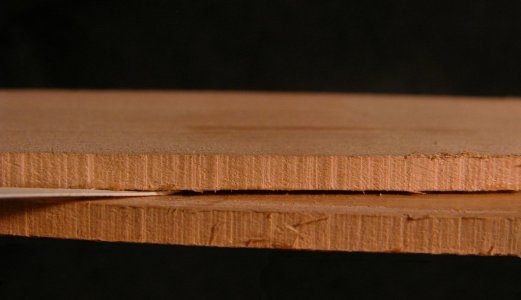
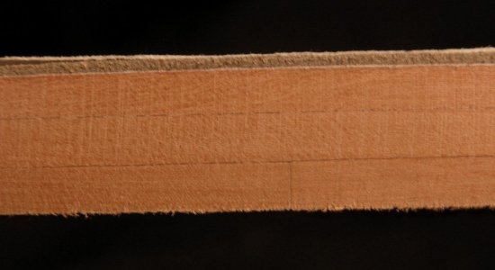
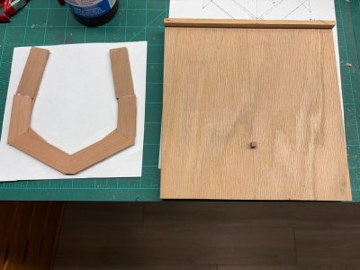
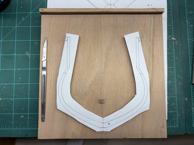
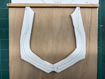
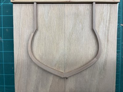
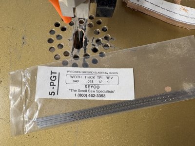

Hi Greg, thank you for sharing this project with us. Would you please explain what a reverse tooth blade is and its advantages?As far as blade selection I have been using a #5 reverse tooth precision ground blade.
On this type of blade there are a few teeth that face upward near the bottom of the blade - the rest of the teeth face downward as normal. The downward teeth do most of the cutting, but the few upward teeth cut on the upstroke. This action provides a cleaner cut with little if any tear-out.Hi Greg, thank you for sharing this project with us. Would you please explain what a reverse tooth blade is and its advantages?
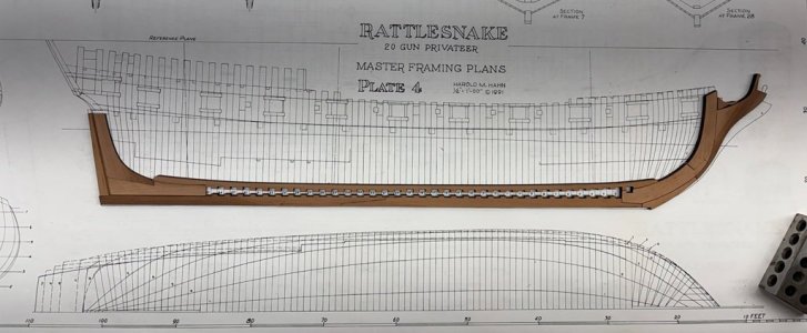
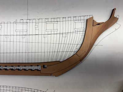
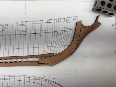
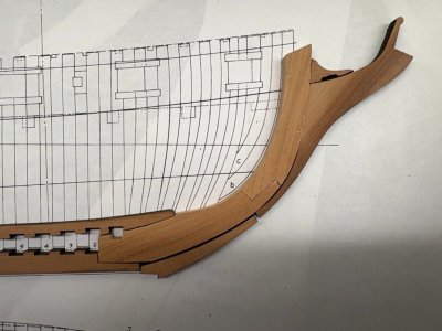
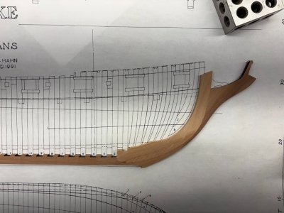
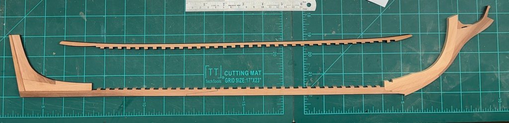
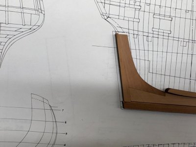


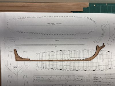
Brilliant and interesting building!Completing the basic assembly of the stem- keel - stern structure turned out to be a bit more challenging than anticipated. Everything had been looking nice when I posted the picture of the laser cut parts set together. However, when the pieces were laid over the master plan I noticed that there were some alignment issues - if the joints were used as cut, the stem did not lie in the correct place.
View attachment 645739
View attachment 645740
If the stem structure was tilted to match the plan, several joints did not line up properly; especially those at the junction with the keel.
View attachment 645741
This generated a lot of discussion in the teacher's lounge. Dave checked his CAD files and they seemed to be much more in line with the plans than the parts I have. It is not clear how the discrepancy got to be. Nevertheless, it needed to be dealt with. It must be noted that the model cannot be constructed if certain aspects are not correct. For example, the top of the stem must be in the correct location or the bowsprit will not have the support it requires. The stem must also cant the correct way else the forward frames and hawse pieces will not fit. Moving down the stem, the mating with the keelson must be preserved. We talked about making some adjustments to the joints in the provided pieces; however, it seemed (at least to me) that the requirements noted above would no longer be met.
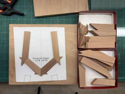
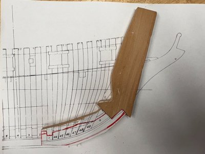
The decision was then made, to replace a couple of the parts and then work the rest in. In the picture below there are two new pieces. The wood used was from a larger piece of 1/4" pear that came with the kit. The lower and left edges were cut to mate with the laser cut keel. The red lines primarily follow the master plan for this piece. But notice that along the top a bump-up has been included and a lower line has been made left of the notch for frame 1. The bump-up and notch modifications are being made to conform to the laser cut keelson. I cut the edge for the joint and matched an oversize piece of wood for the upper part of the stem.
View attachment 645743
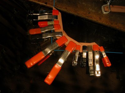
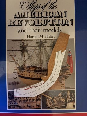
A pattern for the whole stem was rubber cemented in place.
View attachment 645744
Then it was off to the scroll saw and sander to shape these two pieces as a unit. Below is a check that the inner edge of the new pieces conforms to the plans, the keel, and the keelson. (The top of the keelson will be modified slightly when attached so that it blends into the stem as shown in the plans.)
View attachment 645745
The outer / forward edge did not quite match the remaining laser cut pieces at this time:
View attachment 645746
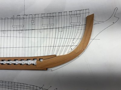
However, it looked like a bit of shaping of the outer edge of the stem would bring the remaining pieces close to where they needed to be. Here it was key to keep the knee of the head in the correct location. Also it can be seen that the forefoot / gripe needed to move up where it joins the keel. Modifications were noted on the pieces and then made with a sander. The result was quite satisfactory, noting that the gripe / forefoot needs a little more work where the false keel will attach:
:
View attachment 645747
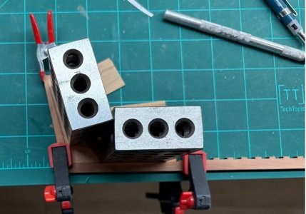
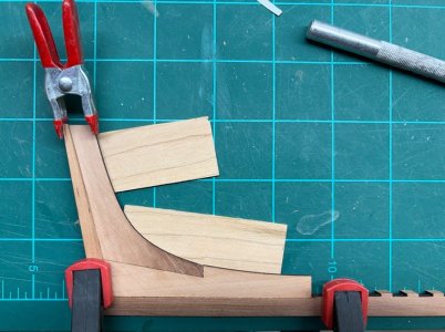
Work at the aft end was a whole lot less complicated. The two pieces forming the deadwood where assembled and then thinned to 1/8". This matches with the space between the pairs of pieces forming the aft half-frames. It also conforms to having reduced the deadwood by the thickness of two hull planks as advised by Hahn. I milled a couple of pieces of wood the correct thickness to position the deadwood centerly on the keel and weighted the deadwood down when gluing up. The stern post was also added at this time:
View attachment 645748
View attachment 645749
Here is where the 'backbone' is of today:
View attachment 645750
The false keel will be fabricated and added next. Then the next challenge commences - tapering the structure and cutting the rabbet.
View attachment 645742