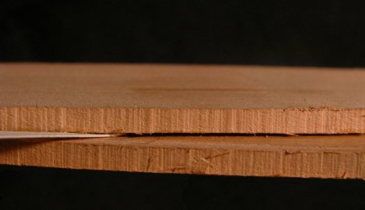
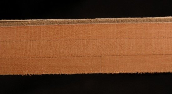
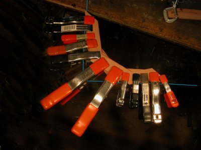
There are still many more frame blanks to be made up as just 4 get done on a given day. But a nice stack of blanks now is on my bench so I am going to begin the frame shaping process simultaneously.
To get going I have made a 'frame assembly jig' as Hahn calls the structure in his book 'The Colonial Schooner'. This jig is shown and described in other writings of his as well. I've used 3/4" plywood to create an 8" x 8" base and a strip of wood is attached to one side forming a lip or overhang of just more than 1/4". Prior to attaching the strip, a line was drawn down the middle of the base and perpendicular to the upper edge. The distance from the
bottom of the master assembly board to the
top of the keel was measured for several frames on the frame plan sheets. One should suffice, but I wanted to make sure I was measuring correctly and there was consistency of this dimension on the plans. For Rattlesnake the distance is 5" and 9/16". This is then the distance needed between the top edge of the board and the top edge of the peg on the jig. The keel tapers for and aft, hence the intersection / joint between frame and keel will vary. The peg was made to accommodate all full frames - it is 3/16" square. A mortise was cut into the plywood and the peg was then inserted and glued in place.
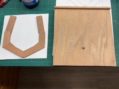
In the picture above, a frame blank is seen rubber cemented to a piece of paper. Excess single thickness material on the blank has been trimmed off. The paper has the shape of frame 19 on the lower side. I held the piece of paper against the frame blank and adjusted its position so the frame outline fit nicely on the blank. Frame 19 - at midship - fits on the blank with little to spare. The back of the paper was marked to indicate where the blank should be set. Rubber cement was then applied and the paper and blank were joined.
It is important that the piece of paper with the frame drawing is left as a solid rectangular sheet. If the paper is cut close to the frame shape inside and out there will likely be a great amount of distortion introduced when gluing to the blank. Not cutting out the shape will minimize the potential problem.
After the paper template is attached to the frame blank, the excess paper is trimmed off. Following Hahn, the next step is to fit the blank to the jig. The notch for the keel is cut first. I did this as a series of perpendicular cuts on a scroll saw. I cut excess material parallel and just above the frame extensions. Final adjustments on the frame extensions were accomplished with a small disc sander. The blank now fit square in the jig.
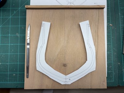
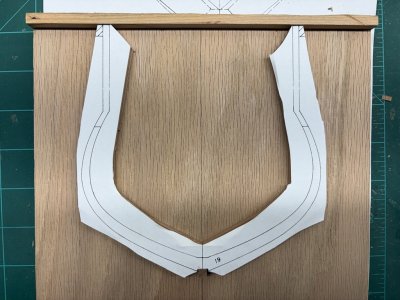
Hahn recommends cutting and shaping the exterior of the frame followed by the interior. I followed his procedure. The exterior shape was cut using a scroll saw and then finished shaped on an oscillating sander. Like work was then done on the interior. I worked up to the lines on the drawing, so technically, there is a small amount of excess material still on the frame that can be removed in a final fairing of the hull.
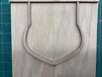
Here is frame 19 after the cutting and shaping. The picture makes it look like the extensions splay - this is not the case, they are each perpendicular to the lip of the jig.
For quite a few days / work sessions there will not be anything new, rather a good deal of repetitious work!