-

Win a Free Custom Engraved Brass Coin!!!
As a way to introduce our brass coins to the community, we will raffle off a free coin during the month of August. Follow link ABOVE for instructions for entering.
-

PRE-ORDER SHIPS IN SCALE TODAY!
The beloved Ships in Scale Magazine is back and charting a new course for 2026!
Discover new skills, new techniques, and new inspirations in every issue.
NOTE THAT OUR FIRST ISSUE WILL BE JAN/FEB 2026
You are using an out of date browser. It may not display this or other websites correctly.
You should upgrade or use an alternative browser.
You should upgrade or use an alternative browser.
HMS Royal Caroline kit ZHL 1/30 (Following the Maarten's RC)
- Thread starter Alex T
- Start date
- Watchers 25
-
- Tags
- royal caroline zhl
ok, now I am really depressed.
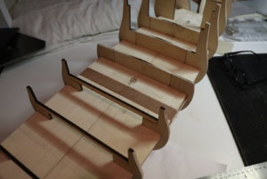
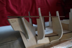
I have just realized that my stern frame does not allow the aft deck to fit: the aft of the frame is too high!
OK, I started to investigate the case. I took pics from John's (@neptune ) blog and I have recognized that we had...different frame elements! Please enjoy the difference: mine frame element is red, the John's is blue.
OK. Now I really fill uncomfortable. Am I supposed to re-cut this frame myself from the ply wood? Hmmmm.
Any suggestions? I really need a nice advice now.
I also recall that @Maarten mentioned "there is a mistake in this stern" when I visited him, but somehow the conversation switched to a different subject and I lost this thread of the discussion. Now I feel pity for this omission...


Hi alex,
It is strange this frame is different. As you wanted to ad the rear cabin it is no issue as you cut it out anyway. After planking the hull attach the plywood stern piece, steam it in the correct shape before fitting and when fitted cut out the frame.
It is strange this frame is different. As you wanted to ad the rear cabin it is no issue as you cut it out anyway. After planking the hull attach the plywood stern piece, steam it in the correct shape before fitting and when fitted cut out the frame.
Hi Aleksandr, if you have the correct pattern, it should be no problem to make a new one... 
G'day Alex, don't cut the stern frame, I think it is just an optical illusion, I have posted some pics below that show mine during construction, I had the same fears as you I thought mine was too high as well, I will try and explain with the help of the pics,
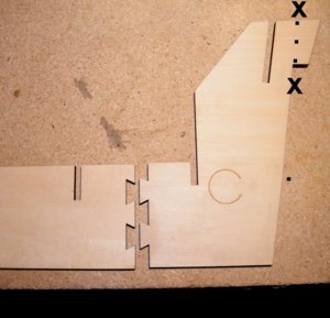
First of all the little tab at the top of the frame between the two letters X needs to be removed before attaching the deck as the
rudder comes up against the back of this frame and if it is not removed now it is a hell of a job to cut it off later,
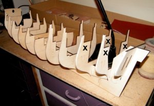
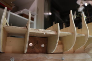
I don't think there is any difference between your frame and mine it just looks it, First there are two beams in the kit that go
across between the X,s, that lift the height in this position,
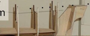
and after the beams are in position the deck should sit in
line with the black dots,
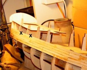
a pic of mine showing the beams above the X,s
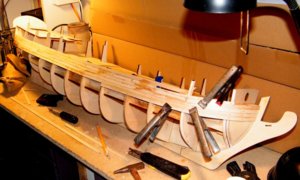
overall view,
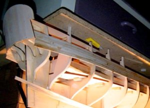
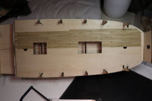
this one shows the ply deck glued in place,
I hope this is clear enough,
best regards John,
.

First of all the little tab at the top of the frame between the two letters X needs to be removed before attaching the deck as the
rudder comes up against the back of this frame and if it is not removed now it is a hell of a job to cut it off later,

I don't think there is any difference between your frame and mine it just looks it, First there are two beams in the kit that go
across between the X,s, that lift the height in this position,

and after the beams are in position the deck should sit in
line with the black dots,

a pic of mine showing the beams above the X,s

overall view,

this one shows the ply deck glued in place,
I hope this is clear enough,
best regards John,
.
This is the difference between me and you, Maarten!After planking the hull attach the plywood stern piece, steam it in the correct shape before fitting and when fitted cut out the frame.
Remember the dialogue with Michelangelo?
– How do you manage to carve such great sculptures?
– You know, I take a piece of marble, and cut out the parts which are not needed...
Dear John,G'day Alex, don't cut the stern frame
Thank you. Yes, it is more clear now.
Just one Q I have:
I see at your picture (I copied it below) that the deck did not fit all beams and it was a gap above the beam #2 (I added numbers to your picture below). At your last picture I see no gap any more. Does it mean that you bent the deck? Or did you file the stern frame down?
In my case the gap is around 8mm (see my picture below) and I have:
- either to bend the deck significantly
- or to cut the stern frame to the red line
- or something in the middle (blue line)
The original drawings show that the aft deck is straight.
Also, if I cut anything, again, I have to make sure that all stern carvings will fit it.
It's like resolving an equation with too many unknown elements.
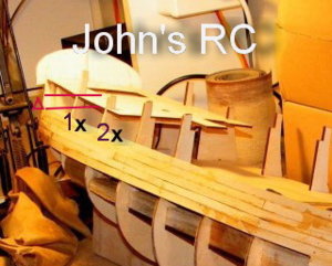
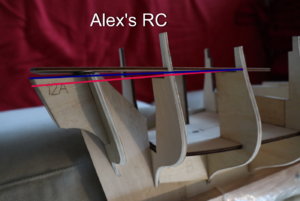
Alex I cannot see the beams, there are two beams that go across frame 10 and frame 11, when you have them in place and the deck sits on top of them your deck will be right, the beams will lift the deck to approx where the two black lines are,
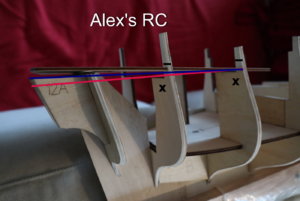
Alex when you put the beams across they will lift the deck to the right position,
.

Alex when you put the beams across they will lift the deck to the right position,
.
Last edited:
Hi alex,
It is strange this frame is different. As you wanted to ad the rear cabin it is no issue as you cut it out anyway. After planking the hull attach the plywood stern piece, steam it in the correct shape before fitting and when fitted cut out the frame.
G'day Alex, I didn't realize that you were going to build in the rear cabin, but if you are Maartens advice is good, plank the hull etc and after you have finished the rear cabin you can then decide if you want to put on the deck or just have deck beams which you can look through and see the cabin details, have a look at Maartens first pages of his build, it looks fantastic, he does a super job,
best regards John,
OMGAlex when you put the beams across they will lift the deck to the right position,
What a shame!
Oh, no.
Dear John,
S O R R Y!
It's a result of a coincidence of several factors:
- Chinese manual
- I split the work with my father: he does the work and I provide the supervision only.
- I interrupted him with this "ship cutting thing" in the middle of building the frame and he forgot about those two beams
Well, it was a learning.
Indeed this ship starts quite differently from anything we had before. I mean that the frame was always a one day work.
OK, Thank to John we are back on rails.
----------------
And Thank you Very Much for this suggestion to remove the part of the frame at the stern to free space for the rudder!
Yes, sure. I do follow Maarten's case. But I was somehow puzzled with this stupid issue with the stern. Yes, I will do as you said.G'day Alex, I didn't realize that you were going to build in the rear cabin, but if you are Maartens advice is good
Ah well it's good you're back on track, there is a lot of thought to be put into this model, it's drove me crazy a couple of times,
Best regards John,
Best regards John,
Or as Donald Duck would say,
We are back on twack,
And his friend said what's a twack,
and Donald said it's what Twain's run on,
And with that it's good night from me and good night from him, enjoy your modelling,
Best regards John,
We are back on twack,
And his friend said what's a twack,
and Donald said it's what Twain's run on,
And with that it's good night from me and good night from him, enjoy your modelling,
Best regards John,
Your process of cutting the hull in two did also happen in reality in the 16th and 17th century.
See here a contempory drawing of a shipyard where a ship was sawn in two to lengthen it.
The proces was two add a new keel part, add some thicker additional frames in between and add an additional layer of planks inside and outside. The old part would be dubbel planked, the new part single planked.
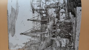
See here a contempory drawing of a shipyard where a ship was sawn in two to lengthen it.
The proces was two add a new keel part, add some thicker additional frames in between and add an additional layer of planks inside and outside. The old part would be dubbel planked, the new part single planked.

Of course, it's all because the VOC company entered the Chinese market. The history always repeats itself, first as a tragedy, then as a farce...Your process of cutting the hull in two did also happen in reality in the 16th and 17th century.
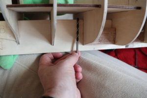
Issue: Making the base. The Chinese method does not look safe at all to me.
Decision:
1. I switch from M3 to M5
2. I will tighten the base to the ship with long (~10cm) bolts.
Steps:
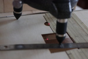
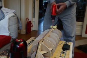
- I made holes through the keel. It was difficult to keep them vertical, so:
- I checked that the ship is horizontal, of I turn it upside down
- I used the laser vertical to set the drill absolutely vertically
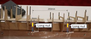
- first run 5mm (I had to buy 90mm drills to get through the keel)
- second run: 9mm from the top for 15mm, just to provide space for the long M5 nuts
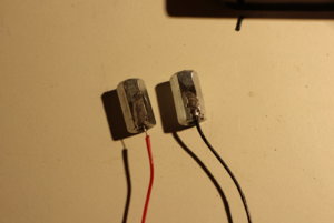
- I bought those long nuts and connected them to the cable along the ship, as the electricity will be provided from the external power source, from the base.
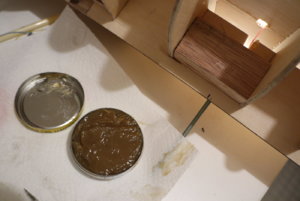
- the nuts were fixed with epoxy resin (nuts and bolts were isolated with grease)


Last edited:
G'day Alex, how much did you insert to the deck before the mast, and will you be moving the hatches forward,
best regards John,
best regards John,


