Cad design Alfred stern cad designing

Dave Stevens (Lumberyard)

Sponsor: dlumberyard
Staff member
Sponsor
Joined
Dec 1, 2016
Messages
5,127
Points
728

in this topic we will explore the methods and process to design a build of the Alfred stern section.
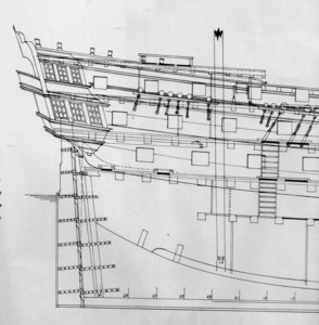
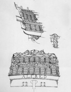
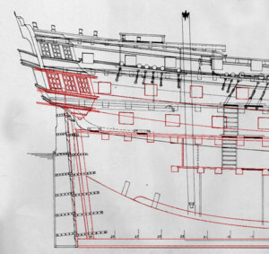
to start out drawings of the stern are needed so going to the original we can get the over all appearance but the original drawings lack the construction detail.

orig1.jpg

orig2.jpg
 
I have heard a comment that anyone or any company using a pre existing set of drawing from a kit or modeling drawings, illustrations from books or elsewhere is cheating because they are using someone else work and avoiding having to do the work themselves. This is so far from the truth it is laughable because the major part of the work it still ahead. The internet is awash with plans, drawings, illustrations and research material I would go as far to say it is all common knowledge, you just have to know where to look.
I will say if anyone got a hold of my CAD files, laser cutting files and settings or STL 3D print files now that is getting an advantage because that is where the real work is. There is no way anyone can get these files unless they hack into my computers or I post them on line. now if I post them on line and find they are being used for a commercial project, well who's to blame for that? ME I posted them.
there are different types of files, the most common is the raster file these are your JPEG, TIFF. or image files, what is needed for lasers, CNC and 3D print and 3D modeling are vector files.

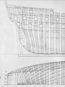
for this topic I am using plans drawn by Harold Hahn these are the raster images, i am not saying it is right or wrong to be using someone's drawings that is beyond the scope of the topic, what i am saying is what your looking at is useless for the project at hand. I need to sit in front of a computer for hours on end and convert these images into working vector files that can be used for laser and CNC machines and 3D modeling. This is where the real work begins and everyone wanting to make anything from these plans has to do the work.

img023a.jpgimg021a.jpgimg019a.jpg
 
if anyone got a hold of my CAD files, laser cutting files and settings or STL 3D print files now that is getting an advantage

To your point Dave, even if someone got your files there would still be work ahead as every CNC machine is different. Different bits, toolpaths, etc. Not all machines use the same G-Code. Laser cutting files may need to be modified to fit the power and size requirements of the laser being used. There are so many variables involved the layman cannot understand. I have been given completely finished CNC toolpaths but still had to spend hours modifying them because they would not work on my specific equipment. For example, the original author may not have used tabs on his toolpath because his CNC machine has a vacuum hold down table. Run the original toolpath on a machine without a vacuum table and some of the small parts will be damaged or sucked into the dust collector.

Good stuff Dave.
 
a raster vs a vector

here is the first image of a raster image in order to do accurate drawings you have to zoom way in and the closer you zoom in the more the image blurs and breaks up. you need a high resolution image to use and actually so does a machine that can use a raster image. a blur to man or machine is useless


img021a2.jpg

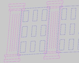
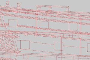
now lets zoom in on a vector file it is the same end window and as you can see no matter how far you zoom in you still get a clean sharp line. it is these lines a machine is using as a 'tool path" it knows exactly where the line is, where it starts and where it stops.

window vector.JPG
 
To your point Dave, even if someone got your files there would still be work ahead as every CNC machine is different. Different bits, toolpaths, etc. Not all machines use the same G-Code. Laser cutting files may need to be modified to fit the power and size requirements of the laser being used. There are so many variables involved the layman cannot understand. I have been given completely finished CNC toolpaths but still had to spend hours modifying them because they would not work on my specific equipment. For example, the original author may not have used tabs on his toolpath because his CNC machine has a vacuum hold down table. Run the original toolpath on a machine without a vacuum table and some of the small parts will be damaged or sucked into the dust collector.

Good stuff Dave.


people who have done the work, talk the talk and walk the walk know better than to believe such statements of a company taking an existing kit and redoing it as their version are people who are avoiding all the work and just copying. Really copying what? all the working files do not come with kits or drawings they have to be created from scratch no matter what the source of the original is.
Mike has been there and done that he know what is really involved.
so onward to create the working files
 
Dave, you are giving away our secrets!!! Just kidding, keep going.. :)

in a way yes but to who? you have to have the machines, the software, the computer work station and most of all the know how.
this i believe is beyond your average model builder but it is a pulling back of the curtain and showing what goes on back stage.
 
this also shows builders like Don Farr who believes a 3D model you can zoom in and out of, walk around it, view parts and how they fit is the ultimate in builders instructions. I say YES! that can be done and we have the technology to do it, and it is being done as we post. The but is the fact it is very complicated and it takes a lot of time and knowledge to do it.
 
YES I KNOW DAVE IT IS EXTREMLY COMPLICATED, will it get easier as time goes by, not sure, some things are meant to be complicated, there are people on this site who through GOD have the skills required to do this TO ME IT IS LIKE CARVING YOU HAVE TO BE BORN WITH THIS SKILL, and also the means to comunicate to others the final use of this, JUST MY 10 CENTS. Don
 
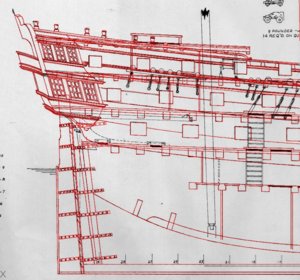
the first step is to trace the original raster file which is in progress here. This is what i call Zen work it is so tedious and labor intensive your mind is focused on splines, lines, arcs, polylines etc you are not aware of what's around you, and this is only the prep work to get working vector files. I have not even thought of creating a 3D model or the laser cutting files or the STL print files. that is a boat load of work that still needs to be done. This project is just the stern section imagine the 100s of hours if this were the entire ship.

tracing1.JPG
 
here is the final tracing of the stern section

tracing2.JPG

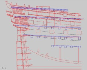
looking close at just the CAD drawing it appears as a jumble of crossing lines

tracing3.JPG

to separate different lines I change colors so the deck lines are in blue

tracing4.JPG

In drafting there is the front, back, top, bottom left and right side views these will have to be developed. The next drawing will be the frame locations.
Here is where the designer/ draftsman has to make calls as what to do.

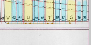
the framing is made up of double bends and single filler frames between the doubles. Here the doubles are in yellow V, U, T, S setting up the cad drawing the arrows are a set equal distance apart. As you can see frame s is right on T is close U is falling short and V is way off. What this is telling me the double frames are not an equal spacing. Same with frames 35 and 36 they fall in the correct space for frames 37 and 38 but 39, 40 and 41 are different.

to go down the entire length of the hull i found the frame thickness and spacing varied. When builders build a hull and CNC or laser cut parts exact they end up with a hull that may or may not match the drawings. This is why, drawings will distort, shrink of expand plus the hand of man if the plans were drawn by hand and not with CAD.

tracing6.jpg
 
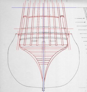
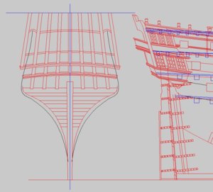
moving on to the stern view i first draw a center line and a base line this is to keep everything level and square. The blue lines are my center and level base line

stern1.JPG

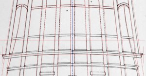
zooming in you see the small arch on the left, when that is mirrored to the right you can see it is off. What i do is trace one side, in this case the left of center then it is mirrored to the right of center. As you look at the drawing you notice the stern timbers on the original do not match up on the left and right of center. The molding started on the left at the top corner and when the line was drawn level across the stern the molding runs slightly up hill.


stern2.JPG


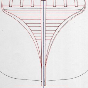
At the lower section when the left was traced then mirrored it missed on the right side.
Over all the original plans are a + or - 1/32 inch or .032 keep in mind Harold drew theses plans by hand with pen and ink so there is bound to be slight errors. In CAD there is no + or - everything is exactly dead on the mark.

stern4.JPG

When your using these original plans and cutting your parts by hand, that is not by a CNC or laser cutter you got to give yourself a little wiggle room for fit and finish. All the slight errors are worked out as you build. So if the plans call for material .125 and you cut it exactly .125 you just removed any adjustments you might need.

Once i have the stern view drawn i will line it up with the side view.

stern3.JPG
 
Back
Top