HOW DID COMPANIES LIKE TRIDENT AND MARISSTEELA< ETC CREATE THERE 3-D INSTRUCTIONS BY THE METHOD YOU DESCRIBE. Don
-

Win a Free Custom Engraved Brass Coin!!!
As a way to introduce our brass coins to the community, we will raffle off a free coin during the month of August. Follow link ABOVE for instructions for entering.
-

PRE-ORDER SHIPS IN SCALE TODAY!
The beloved Ships in Scale Magazine is back and charting a new course for 2026!
Discover new skills, new techniques, and new inspirations in every issue.
NOTE THAT OUR FIRST ISSUE WILL BE JAN/FEB 2026
You are using an out of date browser. It may not display this or other websites correctly.
You should upgrade or use an alternative browser.
You should upgrade or use an alternative browser.
Cad design Alfred stern cad designing
- Thread starter Dave Stevens (Lumberyard)
- Start date
- Watchers 25
HOW DID COMPANIES LIKE TRIDENT AND MARISSTEELA< ETC CREATE THERE 3-D INSTRUCTIONS BY THE METHOD YOU DESCRIBE. Don
Hi Don. In the same manner Dave has been describing to you in this very thread. Every 3D picture in the instructions were meticulously rendered from the CAD drawings that were created when the model was designed from it's original paper plans. 100's of hours of work!!! As much work in the computer as in the actual model itself!!! Wrap your head around that!! Breathe slowly... count backwards from 5... 4, 3, 2, 1... ok Don... got it... calm... there.. Now go out and order your Byrnes Saw.
MIKE UNDERSTAND FULLY, BUT ONE DAY IT WILL HAPPEN, and the BYRNES TOOL NOT A SAW BUT ONE JUST FOR YOU, LOL, BTW MORE KITS FOR ME TO BUILD, but still LOOKING FOR SCRATCH, GILLES OPENED THE DOOR JUST LIKE DAVE OPENED THE VALVE FOR POF, LOVE BOTH SEE IF I CAN DO IT JUSTICE IT IS ABOUT TIME. Don
- Joined
- Dec 1, 2016
- Messages
- 6,372
- Points
- 728

MIKE UNDERSTAND FULLY, BUT ONE DAY IT WILL HAPPEN,
it has already happened I was doing this yeas ago 3D modeling is nothing new the auto industry and many other product design has been using it for years, if you ever watched American Chopper their custom bikes are first created in Solidworks then those files are used in the machine shop.
What is actually holding all this up is not the technology it is the small model ship kit market. It is not big enough and sales of kits do not cover the R&D costs to develop the 3D models as instructions or for 3D printing.
if I expect to be paid or recover cost for a kit of the Alfred stern you can forget it. To be paid for my time plus hire a 3D artist to do the carvings and take all these drawings and render them as a 3D model such a project is thousands of $$ in the hole before it ever goes to production.
So that is the problem in a nut shell if you want to pay $4,000.00 for a kit that might be what it takes for a business to recover costs and return a profit.
it's not the technology it is the cost of these professional programs they are expensive to use, they don't run on a cheap laptops you need a computer work station that can handle the graphics.
time and money is the problem not technology.
just to give you an example Solidworks basic program is $5,290 commercial program can run you $15,270.00 and that is not the cost of the program that is for a subscription paid every year.
Last edited:
AS ALWAYS DAVE AS ALWAYS, so what do you see for the future, do we who advocate for this, just linger in anticapation or stagnate waiting for new developments sad and at the same time excting,. Don DAVE DO YOU REMEMBER THE EARLY DAYS OF SOS WHERE A FEW OF US STARTED SOMETHING THAT WAS BEYOND OUR IMANGNATION WHO WOULD AT THAT TIM SEE THIS COMING, just a thOught
- Joined
- Dec 1, 2016
- Messages
- 6,372
- Points
- 728

well it is now midnight here in Cuyahoga county and the curfew has just taken effect. We are "ordered" not to leave the house. The virus is spreading faster and faster each day.
so I can't ship orders out because all businesses are shut down. looks like it just got real.
A project such as this stern is a fantastic subject well suited for 3D modeling and as Don would like to see a rendered 3D model a builder can look at. from all views and see how it goes together.
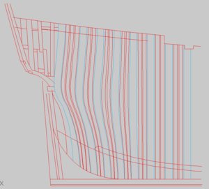
as a 2D drawing looking straight on at the stern you don't see it but there are 3 depth here each a different color.

even a side view does not give you much of a clue.
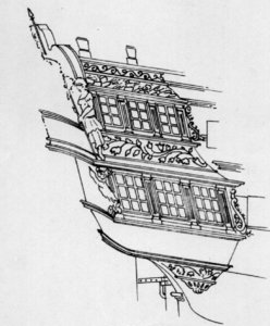
the information is there in the plans as long as you can understand them. That yellow section of windows is actually not really part of the stern it is the back wall of the cabin colored yellow in the drawing.
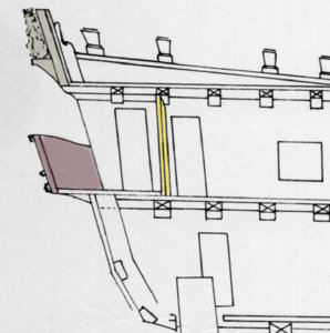
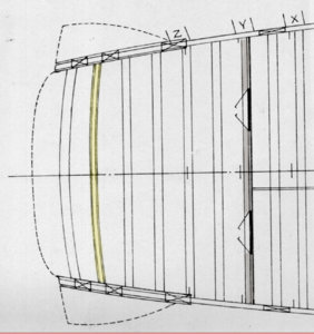
a birds eye view of the cabin you can see where the back wall is located and the balcony
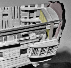
On Harold's model you can see the back wall of the cabin in yellow and the actual stern. At the side are 2 door ways where you can walk from the cabin through the quarter galley and out on the balcony
i agree with Don a rendered 3D model as instructions where a builder can look into the cabin and look all around the stern and with CNC or 3D printed carvings and laser cut timbering set would be the ultimate model kit. Can it be done? sure, can it be made affordable? that is the question.
so I can't ship orders out because all businesses are shut down. looks like it just got real.
A project such as this stern is a fantastic subject well suited for 3D modeling and as Don would like to see a rendered 3D model a builder can look at. from all views and see how it goes together.
as a 2D drawing looking straight on at the stern you don't see it but there are 3 depth here each a different color.

even a side view does not give you much of a clue.

the information is there in the plans as long as you can understand them. That yellow section of windows is actually not really part of the stern it is the back wall of the cabin colored yellow in the drawing.

a birds eye view of the cabin you can see where the back wall is located and the balcony

On Harold's model you can see the back wall of the cabin in yellow and the actual stern. At the side are 2 door ways where you can walk from the cabin through the quarter galley and out on the balcony

i agree with Don a rendered 3D model as instructions where a builder can look into the cabin and look all around the stern and with CNC or 3D printed carvings and laser cut timbering set would be the ultimate model kit. Can it be done? sure, can it be made affordable? that is the question.
- Joined
- Dec 1, 2016
- Messages
- 6,372
- Points
- 728

well its going on 1AM time to call it a day
good nigh fellow builders
good nigh fellow builders
OH WELLNO MATERIALS FOR A WHILE HAVE OTHER SMALL THINGS TO DO, AND WITH GILLES HELP WILL STAR ON SOME OTHER details have enough BEECH FOR 2 more frames, well JESUS HAS GIVEN US THE INTERNET AND AMOZON WILL BE ORDERING SMALL ITEMS FROM THEM CAN NOT SIT AND DAY DREAM IT IS TO FRIEGHTING, GOT TO KEEP BUSY as to my dream DAVE AFFORDABLE WHEN YOU GET 66 or MORE PRE ORDERS, JUST ME, I WILL PM YOU TOMORROW WE HAVE NOT HAD A GOOD DISCUSSION IN A WHILE. TAKE CARE MY FRIEND AND EV ALSO. Don
- Joined
- Dec 1, 2016
- Messages
- 6,372
- Points
- 728

drawing and laser cut files for frames.
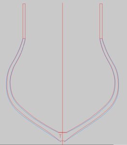
there are 24 frames to be made 8 double frames and 15 single frames. There were 3 ways frames in English ship were built using a lap scarf, chocks and butt to join the futtock ends. There is no doubt about it a simple butt joint is far easier than using chocks, Harold Hahn chose not to use chocks in his model the frames used the butt method.
first step is to draw the frame with the bevels. The frames are drawn from the point of view of standing at the stern and looking toward the bow. The light blue line at the inner part of the frame would be a dotted line and not visible from this point of view.
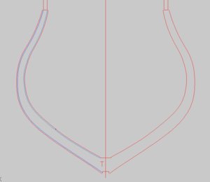
What you are looking at in this drawing is to use the outer blue line and the inside red line in the above drawing. This is the maximum width of the frame which are now the 2 blue lines in the lower drawing. Once again the kurf of the laser plus extra material for cleaning the laser char and extra for building and fitting each frame is added. The tiny dot in the lower left is the laser beam size.
zooming in you can see the size of the laser beam plus extra material along the edge of the frame.
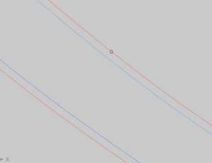
the blue lines are erased and the outer red lines are now used.
The same chock drawing is used for all the frames, this was done so there is no need of having to match each chock with its location in the frame.
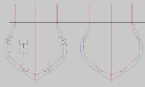
The frame is broken down into its component parts.
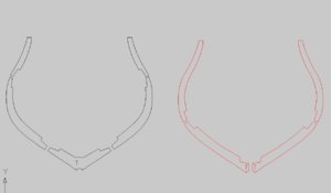
these parts are copied and positioned on a 2 x 24 inch sheet. In this drawing I am missing the cross chock at the floor. There should be 3 chocks for this part of the frame.

you can not see it in the larger drawing so zooming in the gaps become visible. Each and every part has to have these gaps or the part will fall out of the sheet. If all the parts were cut out of the sheets and all put in a bag it would be almost impossible to figure out what part goes to what frame. So it is very important all parts remain in their sheets.
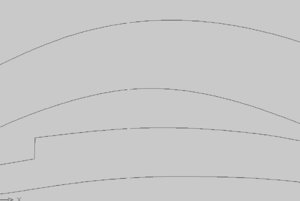
time wise it took about 2 hours from start of drawing the frame to a finished laser cutting file for each frame + 24 frames.
Building frame blanks is a fast and easy way to construct frames. What you do is build a blank, glue a full frame pattern to the blank and cut out the frame. That is fine for hand building frames it does not lend itself to laser cutting frames. Just the opposite apples to the laser cut frames cutting each and every part out by hand then trying to assemble an accurate frame adds a degree of difficulty because you are not cutting the parts out accurately. The reason it works for laser cutting is because cutting the frame parts are dead accurate and you can lay them on a frame pattern and build the frame exactly to the pattern.
there are 24 frames to be made 8 double frames and 15 single frames. There were 3 ways frames in English ship were built using a lap scarf, chocks and butt to join the futtock ends. There is no doubt about it a simple butt joint is far easier than using chocks, Harold Hahn chose not to use chocks in his model the frames used the butt method.

first step is to draw the frame with the bevels. The frames are drawn from the point of view of standing at the stern and looking toward the bow. The light blue line at the inner part of the frame would be a dotted line and not visible from this point of view.

What you are looking at in this drawing is to use the outer blue line and the inside red line in the above drawing. This is the maximum width of the frame which are now the 2 blue lines in the lower drawing. Once again the kurf of the laser plus extra material for cleaning the laser char and extra for building and fitting each frame is added. The tiny dot in the lower left is the laser beam size.

zooming in you can see the size of the laser beam plus extra material along the edge of the frame.

the blue lines are erased and the outer red lines are now used.
The same chock drawing is used for all the frames, this was done so there is no need of having to match each chock with its location in the frame.

The frame is broken down into its component parts.

these parts are copied and positioned on a 2 x 24 inch sheet. In this drawing I am missing the cross chock at the floor. There should be 3 chocks for this part of the frame.

you can not see it in the larger drawing so zooming in the gaps become visible. Each and every part has to have these gaps or the part will fall out of the sheet. If all the parts were cut out of the sheets and all put in a bag it would be almost impossible to figure out what part goes to what frame. So it is very important all parts remain in their sheets.

time wise it took about 2 hours from start of drawing the frame to a finished laser cutting file for each frame + 24 frames.
Building frame blanks is a fast and easy way to construct frames. What you do is build a blank, glue a full frame pattern to the blank and cut out the frame. That is fine for hand building frames it does not lend itself to laser cutting frames. Just the opposite apples to the laser cut frames cutting each and every part out by hand then trying to assemble an accurate frame adds a degree of difficulty because you are not cutting the parts out accurately. The reason it works for laser cutting is because cutting the frame parts are dead accurate and you can lay them on a frame pattern and build the frame exactly to the pattern.
Last edited:
Kurt Konrath
Kurt Konrath
Hey Doc, what about a Blandford stern to go with center section......Very interested to see this. One of the things I've been talking and thinking about is a stern section in a big scale like 1:32.
- Joined
- Dec 1, 2016
- Messages
- 6,372
- Points
- 728

I learned this lesson the hard way when designing and drawing the steam engine. You can not draw parts as individual parts because every part has to fit to another part within the structure. Just a few thousandths off one way or the other and nothing goes together. The size and shape of every part of the structure depends on where it fits and how it matches up to the part it fits to.
The problem is designing parts and the structure there is zero tolerance everything is exact. Well when it comes to fit and finish of the model the hand of man introduces a + or - tolerance it is only natural wood swells and shrinks, warps and moves, glue joints add to the overall structure. so in the design stage a tolerance has to be figured in and that is why you see that extra material added to the frame parts plus .250 was added to the overall height of each frame so a nice even cap rail line can be added to the model.
The problem is designing parts and the structure there is zero tolerance everything is exact. Well when it comes to fit and finish of the model the hand of man introduces a + or - tolerance it is only natural wood swells and shrinks, warps and moves, glue joints add to the overall structure. so in the design stage a tolerance has to be figured in and that is why you see that extra material added to the frame parts plus .250 was added to the overall height of each frame so a nice even cap rail line can be added to the model.
Kurt Konrath
Kurt Konrath
While I was in the USAF, we learned that companies like Boeing are now producing 3D mockups of areas with lots of items, like cockpits and kitchen areas. They use the 3D drawings to check fit interference before going to production with parts to make sure no problems in assembly when parts are completed and costs of rework are expensive.
I like what you are doing, please keep us updated.
I like what you are doing, please keep us updated.
DAVE MY FRIEND WILL WE BE SEEING AKIT SOON FROM THE LUMBERYARD ANY KIT X SECTION STERN SECTION ETC, ETC, ETC. Don
Hi Dave. You are doing a great job explaining a complicated topic. I would like to comment on a couple things you said. Not saying you are wrong, but as you know the technology in this arena continues to improve at a rapid rate. I make these comments based on my own experience, in my own shop, with my own equipment.
1. Laser Kerf - The dot has gotten so small as to be no longer a factor. The drawing software I use (Corel X8) runs the laser dot on the outside of the line and automatically compensates for any kerf. There is no longer a need to manually worry about that in the design process. I even have another lens for my laser that makes the dot twice as small as it currently is. Have never needed to use it.
2. Laser Char - There is no need to compensate for laser char in the design process as this is already factored in by the drawing software. In addition, modern low powered lasers leave very minimal char when the settings have been optimized for the thickness of the wood. Significant char is only seen in mass produced kits where industrial lasers are being used to cut multiple sheets at a time. Modern custom fab shops do not do it this way.
3. Tabs - The small gaps you leave in your drawing to ensure the parts stay attached to their billet. This is common practice with kits and is the simplest solution for shipping parts worldwide without damage. However, these tabs are not required to actually produce the parts on the laser. The nice thing about lasers versus CNC machines is that the material does not need to be clamped down as there is no pressure applied from the cutting action of the laser. CNC jobs must have tabs or the parts could come loose, due to the pressure of a 20,000 rpm mill, and be damaged. I'm sure you are like me and do not enjoy cutting those little tabs off when removing laser cut parts from their billets. I laser cut all my parts with NO TABS and then back the billets with masking tape to keep the parts from falling out. This creates much better parts and reduces workload for the model builder.
A lot of what you guys see in kits are compromises of quantity versus time. New kits like the Trident Alert are truly amazing but small volume fab shops is where some of the niche stuff is you might never hear about. We used to call it "cottage industry" back in my plastic modeling days when everyone started making their own decals or casting resin parts. You are going to see a whole new wave of technical evolution as the price point comes down to consumer level - laser, cnc, 3d printing.
Ok, off my soap box. Dave PLEASE continue.
- Joined
- Dec 1, 2016
- Messages
- 6,372
- Points
- 728

you made very good points Mike and I all comes down to the software being used and the laser. I am using an industrial size laser so all the laser work has to be designed for that laser.
the perfect scenario would be to know what the final machining process would be and design with that in mind. This is being designed for large industrial size production lasers of 800 to 1200 watts with a kurf of .020
also the thickness of the material at 3/8 scale the average material is .400 almost 1/2 thick and small 50 watt lasers can not cut that thick in one pass or cut it fast enough.
it also comes down to time and money. What a 1200 watt industrial laser can cut in 15 minutes may take a small laser 40 minutes to cut.
Last edited:
- Joined
- Dec 1, 2016
- Messages
- 6,372
- Points
- 728

if the shop had the big laser for cutting the thick framing material and a small laser for cutting the delicate work that would be ideal, but it does not so what has to be done is job out the heavy cutting to one shop and the delicate work to another.
here a window cut by a big laser dialed down as far as it goes the window frames are so thin and delicate they crumble, the one on the right was cut by a smaller laser
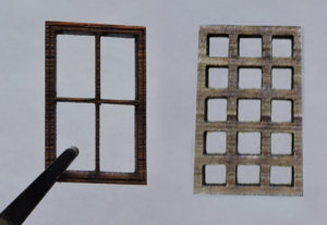
this kind of work is done by a laser that can actually do this sort of work. The machine and the guy running the machine has to know what he is doing and then you have to work with the laser cutter to provide the proper cutting files. It comes down to working as a team.
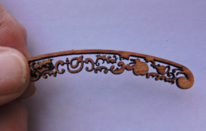
here a window cut by a big laser dialed down as far as it goes the window frames are so thin and delicate they crumble, the one on the right was cut by a smaller laser

this kind of work is done by a laser that can actually do this sort of work. The machine and the guy running the machine has to know what he is doing and then you have to work with the laser cutter to provide the proper cutting files. It comes down to working as a team.


Last edited:
Right on Dave. There is definitely a lot of trial and error involved. By the time one part is what I would call "production ready", there is a pile of prototype parts that did not make it due to various quality control reasons. But the beauty of all this work is, once its done... its done!! Record the settings and you can crank them out over and over with 100% accuracy. Just make sure you have a good way to keep track of all your cutting files. After a couple years it can become a nightmare!!
- Joined
- Dec 1, 2016
- Messages
- 6,372
- Points
- 728

I also notice the type of wood makes a difference so if you change materials or wood a slight tweaking might be necessary
- Joined
- Dec 1, 2016
- Messages
- 6,372
- Points
- 728

DAVE MY FRIEND WILL WE BE SEEING AKIT SOON FROM THE LUMBERYARD ANY KIT X SECTION STERN SECTION ETC, ETC, ETC. Don
it is not likely because the laser cutter I was using to do all the delicate work went out of business so at this time I have no one to do the laser cutting other than the bigger stuff.
another issue is the up front cost to hire an artist to create the 3D STL print files.
- Joined
- Dec 1, 2016
- Messages
- 6,372
- Points
- 728

I am working on 2 different ways to produce a carving set
one is to print the carvings, create a master mold and cast them in resin.
some builders seem to have issues with resin on wooden models
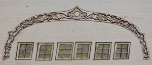
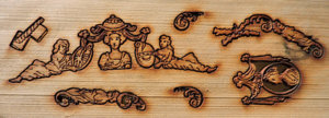
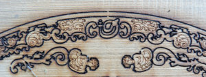
another method is laser cut wood carving blanks
this idea is to produce laser etched blanks and the builder can file, carve, sand blast, the edges and round out the carving. This the blank will give a carver something to start with.
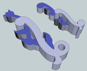
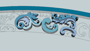
a possible 3rd idea is to use the STL files on a CNC mill and mill out the carvings.
one thing I am thinking of is to create a kit in such a way it gives a builder a chance to try his hand at finishing a carving from a blank. You can't mess it up because once you have the cutting file you can produce them over and over, so a builder can practice and keep trying until its right
one is to print the carvings, create a master mold and cast them in resin.
some builders seem to have issues with resin on wooden models
another method is laser cut wood carving blanks
this idea is to produce laser etched blanks and the builder can file, carve, sand blast, the edges and round out the carving. This the blank will give a carver something to start with.


a possible 3rd idea is to use the STL files on a CNC mill and mill out the carvings.
one thing I am thinking of is to create a kit in such a way it gives a builder a chance to try his hand at finishing a carving from a blank. You can't mess it up because once you have the cutting file you can produce them over and over, so a builder can practice and keep trying until its right

