Cad design Alfred stern cad designing

So do you plan to correct the errors in CAD or leave the as per the original plans?

there are two types of drawings going on what you are looking at is the original drawing done by Harold Hahn done on tissue paper. These drawings were copied and a master made that all others were then reproduced from. A + or - was not that big of a concern as the drawings gave the model builder a frame work to build in. As the model is being built the builder will tweak and fit all the parts

018.JPG

Later on Harold switched from using tissue paper to mylar which was far more stable and gave sharper pen lines.

026.JPG028.JPGa6.jpg

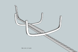
the way Harold drew his plans can be seen here, a master plan was drawn this is the original master drawings for the Oliver Cromwell

A004.jpg

zooming in you see the graph

A04.jpg

pieces of mylar were laid over the graph and each frame was drawn

A003.jpg

these are drawings done for model building and once the original drawings are done a master is made and from that master blue print copies are made for reproduction.

NOW

what is being done with the Alfred stern is drawings are done for "machine work" so all these small imperfections are worked out and precise X,Y,Z are set so the machine knows where everything is, where it starts and where it ends. This is a totally different approach to drawing than the originals done by Harold.

everything comes down to numbers a machine sees 1.25600 <0 1.4482 . 90 there is no mistake, no sort of close it is exactly what it says.

so to answer the question what started out as a hand drawn alfred stern will end up as an exact machine drawing
 
Last edited:
things to do
draw out the frame shapes
break down the frames into their parts
create a laser cutting file for the parts and lay them out on sheet stock

at the stern
create a stern template
create all the stern windows

draw out the deck framing then break it down into laser cutting files

test different ideas for the carvings
CNC carved
laser carved
3D printed
semi cut blanks so a builder can finish the details
 
Hi Dave, one question, is there a difference between what is shown ON THE 42 POUND CARRONADE, and what you are showing if so what as always THANKS Don
 
Hi Dave, one question, is there a difference between what is shown ON THE 42 POUND CARRONADE, and what you are showing if so what as always THANKS Don

what you are seeing on the carronade topic is 3D drawings these type of drawings are done in programs like fusion360 and they start out as 3D modeling.
what you see in the bomb vessel topic done by Jeff are isometric illustrations which are not in anyway CAD drawings,

I could 3D model the stern here but what I need are 2D cutting files for CNC or laser cutters. From these 2D files a 3D model can be created. This project requires a certain amount of designing before any finished 3D model or cutting files can be done.
 
to draw out the stern windows each and every window is a different shape

window7a.jpg

stern windows are not square if you put one pane in a square box you can see the actual shape.

window6.JPG

once the windows are drawn to fit the stern they have to be set up for cutting. What you are looking at is those circles are the size of the laser beam and if you cut what you drew the laser will follow your exact window drawing which is the black lines. Notice the space between the panes at the top is much narrower than the space directly below, this is because the kurf of the beam cut into the frames.

WINDOW3a.jpg


Once the exact window is drawn you have to create a tool path, the magenta lines are actually the path the laser will follow. But if you are going to 3D print the windows then you would use the original drawing which is drawn in black.

WINDOW4a.jpg

here you can see the difference from the original window drawing and the window set up for laser cutting.

window5a.jpg

the steps in creating stern windows is
1 set up the stern timbering
2 draw the windows to fit the timbering
3 rework the originals and create a tool path.
4 do the math to make sure you figure in the tool path, the width of the kurf, and cleaning the laser char.
 
DAVE, I UNDERSTAND NOW WHAT YOU WERE SAYING BOY LOTS OF TIME SPENT, THANKS FOR EXPLAINING. Don

if you good with CAD and drafting you might spend around a 100 or so hours in front of a computer designing and drawing. This is only the basic CAD designing i have not even considered the 3D modeling part. But I did do a couple tests on the windows as 3d models, and played around with the pillars and craving blank in the lower corner.
I am thinking 10 steps ahead and how i can make different parts. Notice the leaves on the carvings they have different levels, a laser can etch different depths, so if the carving blank was laser cut with different levels this gives a builder a pattern to finish off by blending the different depth.

alfred stern.jpg
 
Last edited:
Hope this eventually turns into a kit.

it is possible to turn this or any of the stern sections from the Hahn models into kits. Because the Lumberyard is, well a lumber business, I job out the laser cutting, 3D printing, computer modeling and production mold making to experts in their field. Even though i can do the computer modeling myself, a bit slow at it, so sometimes it is better to turn the project over to people who are fast and skilled. As they do their thing i can move onto other aspects of design work.
At this time i am going at it as just a design project and demo on basic design and drawing, perhaps someone might come forward and pick up on the project or part of it.
 
Hello Dave,
I have been wanting to build the sister ship Warrior, and have the complete set of Reverend Romero's books and Hahn plans in 1/64 scale.

Would be tempted to purchase a framing set from you if this ever developed into a kit for sale.

cheers Brian.
 
YES MIKE AND A BYRNES SAW TOO, MIKE SAVING THE MONEY AND MT PATIENCE( WITCH I NEVER HAD IN MY LIFE SO WHY START NOW) FOR THE TRIDENT HAS IT ALL AND I MEAN ALL BUT WHO KNOWS WHEN, RIGHT NOW STOCKING UP AND ORDERING MATERIALS A LOT SO DO NOT RUN OUT, I AM ON PERMANET QUAEANTEEN FOR THE PAST 7 PLUS YEARS NOT VOLUNTARY EITHER ONE DAY OUT FOR4 HORS ONCE A MONTH HA, HA, WELCOME TO MY WORLD PEOPLE LOL
 
MIKE ONE DAY THIS WEEK I WILL SEND YOU A RE-CAP OF HOW I SEE THINGS IN THIS HOBBY, will send it to you BY PM AND FORGIVE THE GRAMMER< SPELLING ETC< EYE HAD AND BRAIN COORDINATION NOT WHAT IT ONCE WAS, BUT ACCEPTABLE. THANKS MY FRIEND Don
 
DAVE ONE THING THAT I AM NOT GETTING THROUGH IN THIS OLD HEAD OF MINE, I STILL CAN NOT UNDERSTAND FOR INSTANCE THE WORK ON THE CARRONADE, AND THE ONE THAT YOU SENT ME ON THE CAUSTIC THAT STARTED THE BALL ROLLING IN MY HEAD, THEY SEEM TO ME QUICK AS I SEE IT OR AM I MISSING SOMETHING HERE WITCH IS HIGHLY LIKELY. THANKS Don
 
DAVE ONE THING THAT I AM NOT GETTING THROUGH IN THIS OLD HEAD OF MINE, I STILL CAN NOT UNDERSTAND FOR INSTANCE THE WORK ON THE CARRONADE, AND THE ONE THAT YOU SENT ME ON THE CAUSTIC THAT STARTED THE BALL ROLLING IN MY HEAD, THEY SEEM TO ME QUICK AS I SEE IT OR AM I MISSING SOMETHING HERE WITCH IS HIGHLY LIKELY. THANKS Don


quick? well yes I can sit down and create a 3D part in minutes from existing CAD drawings, to create an entire ship from scratch including cutting or printing files that is another story and 100s of hours.
As an example here are the CAD drawings for the Alvin Clark a 1840 lake schooner

plan1.jpg

I have the vector files which is many, many hours of work, but once I have those files I can create 3D parts and images. like this within minutes here is a part for a winch

pull1.png

BAM! that took all of a minute

pull4.png

i can make a 3d keel from the vector CAD files

plan6.jpg

I can make a couple frames and set them on the keel.

keel8.pngkeel3.pngkeel4.pngkeel5.pngkeel6.pngkeel7.pngkeel9.pngkeel10.png

say you ask me to create a 3D image of the stern of the ship your working on. Yes I can do that as long as I have a high resolution image of the plans or a CAD file to work from. If not I have to create the 3d model from scratch. There is a lot of prep work involved. I can use a program like sketchup and import a JPEG image, trace it and create a 3D file of the object, but again it takes time.
model building is the same no matter if it is on the computer or on your work table, all the parts have to be created and the model built. Time is a big factor like sitting in front of a computer hours on end. Like the Alfred stern I work on it a few hours late at night and may not get back to it for days or weeks. I just can not get up in the morning and spend 10 house a day for days drawing.
It would be a great service if a builder gets stuck on a build and posts a request for a 3D model so the builder can see it from all views, that is one tall order and you would have to be really good and really fast to do that.
Some thing are really easy and fast like creating a cannon that can be done on 5 minutes.keel1.png
 

Attachments

  • keel2.png
    keel2.png
    52.8 KB · Views: 8
Last edited:
I AM GETTING A PICTURE OF THIS I THINK, IT SEEMS LIKE A ARCITECT DRAWING A HOUSE PLAN THE OLD WAY, WHEN FINISHED YOU CAN GET AS MANY SETS PRINTED AS YOU NEED FOR THE ACTUAL CONSTRUCTION, AM I CORRECT,,,,,, ANOTHER QUESTION LET US SAY SOMEONE HAS A SET OF PLANS AND HE SENDS THEM TO YOU DOES THAT ELIMANTE ANY TIME, I SURE DO NOT UNDERSTAND ANY OF THE TECH. STUFF AT ALL,JUST THAT SIDE OF MY BRAIN DOES NOT WORK BUT I SURE DO KNOW WHAT THE FINAL OUT COME CAN BE, LIKE BRIAN SAID WHY NOT A KIT I THINK IT WOULD GO LIKE HOT CAKES, I KNOW THAT YOU ARE HAVING ONE HELL OF A GOOD TIME RIGHT NOW IT SEMS YOU ARE REALLY ENJOYING THIS TIME IN THE HOBBY. Don
 
,, ANOTHER QUESTION LET US SAY SOMEONE HAS A SET OF PLANS AND HE SENDS THEM TO YOU DOES THAT ELIMANTE ANY TIME

if the plans are a computer vector file it would save a lot of time BUT if they were paper plans or an image of a plan then no because all the work is in creating that working vector file. Or if it is a STL file you can render it then you can create all kinds of 3D images from the original STL, but then again creating that STL file is a lot of work.

I AM GETTING A PICTURE OF THIS I THINK, IT SEEMS LIKE A ARCITECT DRAWING A HOUSE PLAN THE OLD WAY, WHEN FINISHED YOU CAN GET AS MANY SETS PRINTED AS YOU NEED FOR THE ACTUAL CONSTRUCTION, AM I CORRECT,,,,,,

yes sort of once you have the original vector file created in the computer you can convert that files into all sorts of things like 3D rendered images, cutting files, modeling plans, 3D model. it is getting that first original file. This is why the rumor of people taking an existing set of plans or a kit and copying it to save time is bunk! there is a ton of work to created the computer working files and those are the files you need.
 
Back
Top