true storyI wouldn't necessarily say this is the standard; it is a standard, but not for us, common mortals...
-

Win a Free Custom Engraved Brass Coin!!!
As a way to introduce our brass coins to the community, we will raffle off a free coin during the month of August. Follow link ABOVE for instructions for entering.
You are using an out of date browser. It may not display this or other websites correctly.
You should upgrade or use an alternative browser.
You should upgrade or use an alternative browser.
BALDER, Vlaardingen Herring Lugger from 1912, scratch build scale 1:50 Plate-On-Frame
- Thread starter Peter Voogt
- Start date
- Watchers 61
A few parts still need to be installed on the bow and foredeck: the three supports for the jib boom:
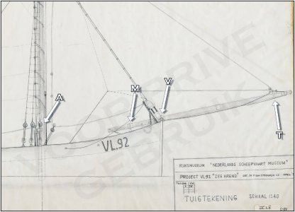
In this drawing from the Amsterdam archives:
When the jib boom is extended, it rests on the forward (V) and middle (M) supports.
When the jib boom is retrieved, it rests on the forward (V) and aft (A) supports. It then hangs freely above the middle (M) support.
Because some confusion may arise later, I've also indicated the so-called traveler with the letter "T." This is a ring with hooks that hangs around the jib boom in front of the forward support. It guides the tack of the jib into the correct position.
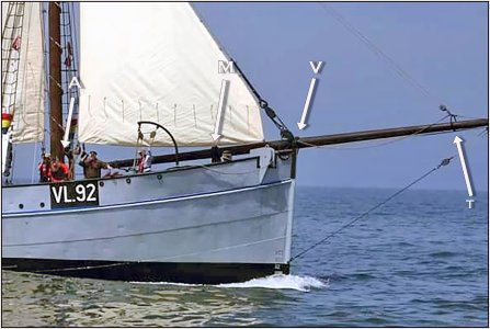
Also indicated here in the photo with the "T." However, without the jib. The aft (A) support is on the port side besides the main mast.
These are the three supports, where the jib boom is resting:
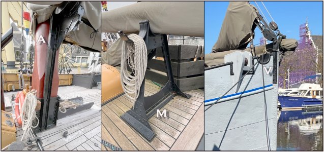
When resting it's above the middle support (M). That's why the opening is hinged.
First, I started working on the forward stay. When constructing it, I have to take into account that I'll also use the parts to clamp the two halves of my model together at the bow.
Some images for clarification:
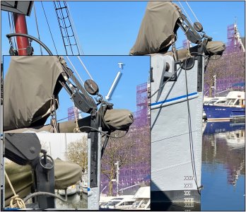
- The "T" arrow on the largest insert is the traveler, because it looks like the hook block is attached to the forward stay. But that's the hook block for the jib head halyard. I'll explain that in more detail once I get to the rigging, as well as the other ropes and cables in the image.
- On the small insert, you can see the wedge with the locking ring inserted through the pin. The pin is locked on the other side in the jib ring.
Indeed: they didn't secure the ring properly around the pin.
- The pin also holds the arm of the large metal 4-sheave forestay block, which lowers the mainmast, between the two bow plates. As I described at the beginning of this report, when fishing and the ship with its mast lowered keeps the nets taut.
A drawing and photo of the rear view of the support mounted on the port side of the stem:
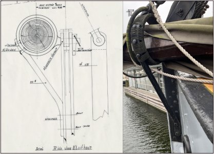
The ring has an inside diameter of 340 mm and is covered with rope. This allows the jib boom to slide through easily and prevents damage.
In the extended position, the jib boom is 300 mm thick at the location of this support and is then almost enclosed.
First, I drilled a 1 mm hole in a piece of 2 mm rod and beveled the end.
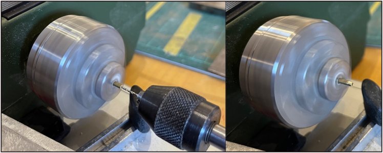
Then I sawed it off to a length of 2 mm to be used as a collar.
My soldering skills were refreshed:
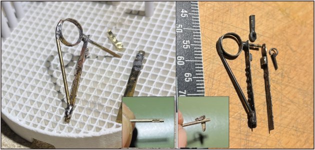
The collar sits between the ring and the port side plate. A 1 mm pin goes through the collar and into the ring. The ring has an inside diameter of 1:50 of 340 mm = 6.8 mm. Above the pin is the arm for the large forestay block that will be made later. The loose plate can also be slid onto the pin. The whole thing is then secured with a wedge that fits into a slot in the pin. It took three attempts before I had a 0.4 mm slot milled into the 1 mm pin .......
The ring covered with 0.35 mm black wire:
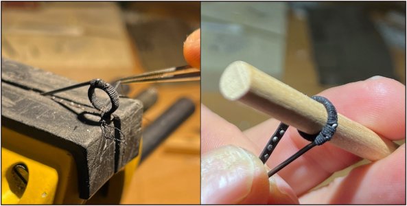
The opening was fitted with a piece of 6 mm spar. The diameter of the jib boom at that location in the extended position.
Then it was time to see if theory matched practice again. Exciting, because on either side of the stem, both plates had to be secured in the right place:
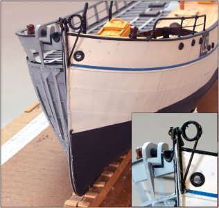
The starboard section slid neatly over the pin, and the wedge locked it in place.
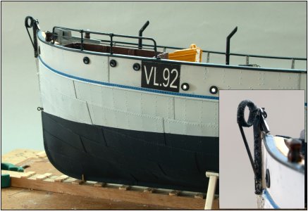
Yet another action I have to perform if I want to separate the two parts again.
Regards, Peter

In this drawing from the Amsterdam archives:
When the jib boom is extended, it rests on the forward (V) and middle (M) supports.
When the jib boom is retrieved, it rests on the forward (V) and aft (A) supports. It then hangs freely above the middle (M) support.
Because some confusion may arise later, I've also indicated the so-called traveler with the letter "T." This is a ring with hooks that hangs around the jib boom in front of the forward support. It guides the tack of the jib into the correct position.

Also indicated here in the photo with the "T." However, without the jib. The aft (A) support is on the port side besides the main mast.
These are the three supports, where the jib boom is resting:

When resting it's above the middle support (M). That's why the opening is hinged.
First, I started working on the forward stay. When constructing it, I have to take into account that I'll also use the parts to clamp the two halves of my model together at the bow.
Some images for clarification:

- The "T" arrow on the largest insert is the traveler, because it looks like the hook block is attached to the forward stay. But that's the hook block for the jib head halyard. I'll explain that in more detail once I get to the rigging, as well as the other ropes and cables in the image.
- On the small insert, you can see the wedge with the locking ring inserted through the pin. The pin is locked on the other side in the jib ring.
Indeed: they didn't secure the ring properly around the pin.
- The pin also holds the arm of the large metal 4-sheave forestay block, which lowers the mainmast, between the two bow plates. As I described at the beginning of this report, when fishing and the ship with its mast lowered keeps the nets taut.
A drawing and photo of the rear view of the support mounted on the port side of the stem:

The ring has an inside diameter of 340 mm and is covered with rope. This allows the jib boom to slide through easily and prevents damage.
In the extended position, the jib boom is 300 mm thick at the location of this support and is then almost enclosed.
First, I drilled a 1 mm hole in a piece of 2 mm rod and beveled the end.

Then I sawed it off to a length of 2 mm to be used as a collar.
My soldering skills were refreshed:

The collar sits between the ring and the port side plate. A 1 mm pin goes through the collar and into the ring. The ring has an inside diameter of 1:50 of 340 mm = 6.8 mm. Above the pin is the arm for the large forestay block that will be made later. The loose plate can also be slid onto the pin. The whole thing is then secured with a wedge that fits into a slot in the pin. It took three attempts before I had a 0.4 mm slot milled into the 1 mm pin .......
The ring covered with 0.35 mm black wire:

The opening was fitted with a piece of 6 mm spar. The diameter of the jib boom at that location in the extended position.
Then it was time to see if theory matched practice again. Exciting, because on either side of the stem, both plates had to be secured in the right place:

The starboard section slid neatly over the pin, and the wedge locked it in place.

Yet another action I have to perform if I want to separate the two parts again.
Regards, Peter
Last edited:
- Joined
- Jul 18, 2024
- Messages
- 459
- Points
- 323

“First I drilled …” … of course you did. Simple.
On our bell curve, you are wayyyyyy right.
On our bell curve, you are wayyyyyy right.
Inspired and inspiring. I especially respect the conviction that the scale needs to be right.
With every new post you make, Peter, I find myself wondering, “What’s he going to come up with this time?” As always, Bravo mon ami!
This again looks very convincing like real forged iron rods up close.
Your work really stands out at macro images.
Your work really stands out at macro images.
Hi Peter,
Tricky job, beautifully executed.
Cheers,
Stephen.
Tricky job, beautifully executed.
Cheers,
Stephen.
Thanks you all for the compliments, nice words and the others for the 'likes'.
 . About the bell curve, Marco: I hope I'm not at the top now .....
 And there was also this technical drawing with all the measurements:
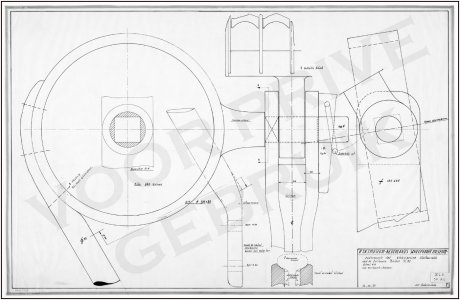
Then I couldn't avoid having to recalculate everything.


 That sometimes makes the challenge greater .......
Regards, Peter
By every part you have the start action ....... Often not the most interesting ...“First I drilled …” … of course you did. Simple.
On our bell curve, you are wayyyyyy right.

That's why the build is in scale 1:50 and not "+/- 1:50", Paul.Inspired and inspiring. I especially respect the conviction that the scale needs to be right.

Then I couldn't avoid having to recalculate everything.
Yep, Stephen, I've written it before "It's all in the details".Again, great details
For your peace of mind, Jim: the next are just 2 other supports .......With every new post you make, Peter, I find myself wondering, “What’s he going to come up with this time?” As always, Bravo mon ami!

Most of the time the macro's are killing, MaartenThis again looks very convincing like real forged iron rods up close.
Your work really stands out at macro images.
There were more tricky items to make it indeed a tricky job, Stephen.Hi Peter,
Tricky job, beautifully executed.
Cheers,
Stephen.
Regards, Peter
- Joined
- Sep 3, 2021
- Messages
- 5,101
- Points
- 738

Making slots, using a drill: monk's work and low probability of first time right.It took three attempts before I had a 0.4 mm slot milled into the 1 mm pin .......
Your rendition of the boom support very closely resembles the full-scale example, to the extend that when looking at a picture it'll be hard to see whether it's the model or the full scale Balder.
What they all say Peter.A few parts still need to be installed on the bow and foredeck: the three supports for the jib boom:
View attachment 552471
In this drawing from the Amsterdam archives:
When the jib boom is extended, it rests on the forward (V) and middle (M) supports.
When the jib boom is retrieved, it rests on the forward (V) and aft (A) supports. It then hangs freely above the middle (M) support.
Because some confusion may arise later, I've also indicated the so-called traveler with the letter "T." This is a ring with hooks that hangs around the jib boom in front of the forward support. It guides the tack of the jib into the correct position.
View attachment 552472
Also indicated here in the photo with the "T." However, without the jib. The aft (A) support is on the port side besides the main mast.
These are the three supports, where the jib boom is resting:
View attachment 552473
When resting it's above the middle support (M). That's why the opening is hinged.
First, I started working on the forward stay. When constructing it, I have to take into account that I'll also use the parts to clamp the two halves of my model together at the bow.
Some images for clarification:
View attachment 552474
- The "T" arrow on the largest insert is the traveler, because it looks like the hook block is attached to the forward stay. But that's the hook block for the jib head halyard. I'll explain that in more detail once I get to the rigging, as well as the other ropes and cables in the image.
- On the small insert, you can see the wedge with the locking ring inserted through the pin. The pin is locked on the other side in the jib ring.
Indeed: they didn't secure the ring properly around the pin.
- The pin also holds the arm of the large metal 4-sheave forestay block, which lowers the mainmast, between the two bow plates. As I described at the beginning of this report, when fishing and the ship with its mast lowered keeps the nets taut.
A drawing and photo of the rear view of the support mounted on the port side of the stem:
View attachment 552475
The ring has an inside diameter of 340 mm and is covered with rope. This allows the jib boom to slide through easily and prevents damage.
In the extended position, the jib boom is 300 mm thick at the location of this support and is then almost enclosed.
First, I drilled a 1 mm hole in a piece of 2 mm rod and beveled the end.
View attachment 552476
Then I sawed it off to a length of 2 mm to be used as a collar.
My soldering skills were refreshed:
View attachment 552477
The collar sits between the ring and the port side plate. A 1 mm pin goes through the collar and into the ring. The ring has an inside diameter of 1:50 of 340 mm = 6.8 mm. Above the pin is the arm for the large forestay block that will be made later. The loose plate can also be slid onto the pin. The whole thing is then secured with a wedge that fits into a slot in the pin. It took three attempts before I had a 0.4 mm slot milled into the 1 mm pin .......
The ring covered with 0.35 mm black wire:
View attachment 552478
The opening was fitted with a piece of 6 mm spar. The diameter of the jib boom at that location in the extended position.
Then it was time to see if theory matched practice again. Exciting, because on either side of the stem, both plates had to be secured in the right place:
View attachment 552481
The starboard section slid neatly over the pin, and the wedge locked it in place.
View attachment 552480
Yet another action I have to perform if I want to separate the two parts again.
Regards, Peter
Making slots, using a drill: monk's work and low probability of first time right.
Your rendition of the boom support very closely resembles the full-scale example, to the extend that when looking at a picture it'll be hard to see whether it's the model or the full scale Balder.
You both also thanks for this compliments and nice words, Johan and Grant.What they all say Peter.
Regards, Peter
I already want to make masts and rigging... sails and everything related to this... But that's still so far away... You're doing great, I'm glad to follow your updates!A few parts still need to be installed on the bow and foredeck: the three supports for the jib boom:
View attachment 552471
In this drawing from the Amsterdam archives:
When the jib boom is extended, it rests on the forward (V) and middle (M) supports.
When the jib boom is retrieved, it rests on the forward (V) and aft (A) supports. It then hangs freely above the middle (M) support.
Because some confusion may arise later, I've also indicated the so-called traveler with the letter "T." This is a ring with hooks that hangs around the jib boom in front of the forward support. It guides the tack of the jib into the correct position.
View attachment 552472
Also indicated here in the photo with the "T." However, without the jib. The aft (A) support is on the port side besides the main mast.
These are the three supports, where the jib boom is resting:
View attachment 552473
When resting it's above the middle support (M). That's why the opening is hinged.
First, I started working on the forward stay. When constructing it, I have to take into account that I'll also use the parts to clamp the two halves of my model together at the bow.
Some images for clarification:
View attachment 552474
- The "T" arrow on the largest insert is the traveler, because it looks like the hook block is attached to the forward stay. But that's the hook block for the jib head halyard. I'll explain that in more detail once I get to the rigging, as well as the other ropes and cables in the image.
- On the small insert, you can see the wedge with the locking ring inserted through the pin. The pin is locked on the other side in the jib ring.
Indeed: they didn't secure the ring properly around the pin.
- The pin also holds the arm of the large metal 4-sheave forestay block, which lowers the mainmast, between the two bow plates. As I described at the beginning of this report, when fishing and the ship with its mast lowered keeps the nets taut.
A drawing and photo of the rear view of the support mounted on the port side of the stem:
View attachment 552475
The ring has an inside diameter of 340 mm and is covered with rope. This allows the jib boom to slide through easily and prevents damage.
In the extended position, the jib boom is 300 mm thick at the location of this support and is then almost enclosed.
First, I drilled a 1 mm hole in a piece of 2 mm rod and beveled the end.
View attachment 552476
Then I sawed it off to a length of 2 mm to be used as a collar.
My soldering skills were refreshed:
View attachment 552477
The collar sits between the ring and the port side plate. A 1 mm pin goes through the collar and into the ring. The ring has an inside diameter of 1:50 of 340 mm = 6.8 mm. Above the pin is the arm for the large forestay block that will be made later. The loose plate can also be slid onto the pin. The whole thing is then secured with a wedge that fits into a slot in the pin. It took three attempts before I had a 0.4 mm slot milled into the 1 mm pin .......
The ring covered with 0.35 mm black wire:
View attachment 552478
The opening was fitted with a piece of 6 mm spar. The diameter of the jib boom at that location in the extended position.
Then it was time to see if theory matched practice again. Exciting, because on either side of the stem, both plates had to be secured in the right place:
View attachment 552481
The starboard section slid neatly over the pin, and the wedge locked it in place.
View attachment 552480
Yet another action I have to perform if I want to separate the two parts again.
Regards, Peter
Thanks, Sergey. I also see so many things I want to tackle. But I'm sticking with my plan... which I've adjusted many times.I already want to make masts and rigging... sails and everything related to this... But that's still so far away... You're doing great, I'm glad to follow your updates!
Regards, Peter
But I'm sticking with my plan... which I've adjusted many times


Nothing is more fickle than a human being ....
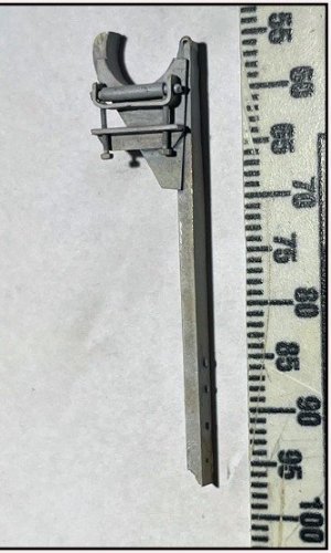
The aft support for the jib boom:
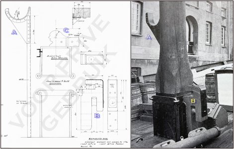
This is located on the port side of the mast tube. Once the three supports are in place, the line-guide block (B) and the nail bank (C) must also be attached to the mast tube.
Apparently, this guide roller was later added to the rear:
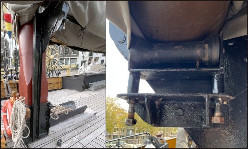
Then the jib boom can be partially rolled in and out. The roller can be adjusted to the correct height with two bolts so that the jib boom just doesn't scrape the bottom.
I'm getting better at working with and soldering of the brass. I now solder with a flame that I adjust just between blue and yellow. This allows me to control the melting of bits of solder and without deforming the brass. Or even melting it, because that also happened with a blue flame.
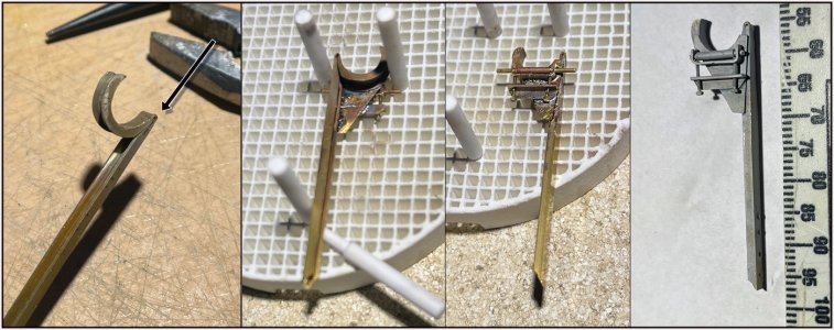
In the left photo: I first heated the U-profile so that I could bend it into the 6 mm internal curve. I filed the double angle at the arrow so that the profile could then bend to the correct angle.
Then, on the rear, I soldered the support plate and guide roller with the adjusting plate and primed it.
After spraying the support glued on the side of the mast tube:
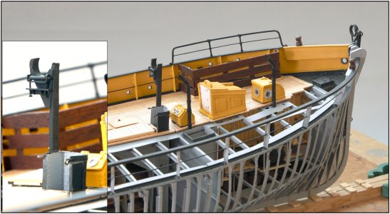
I used 2 mm, 6x5 bolts for adjustment. However, it isn't functional this time......
For alignment, I used a piece of 250x6 mm round timber:
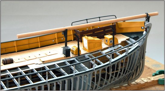
That's also the size of the jib boom (12.5 m x 30 cm). It just hasn't been sanded into shape yet.
From the other side:
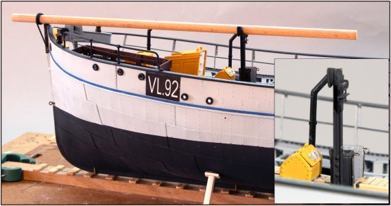
On the Balder, the support is attached to the mast tube with 2x3 bolts. My M0.6 bolts are still a bit too large. That's why I attached it with 4 bolts.
Regards, Peter

This is located on the port side of the mast tube. Once the three supports are in place, the line-guide block (B) and the nail bank (C) must also be attached to the mast tube.
Apparently, this guide roller was later added to the rear:

Then the jib boom can be partially rolled in and out. The roller can be adjusted to the correct height with two bolts so that the jib boom just doesn't scrape the bottom.
I'm getting better at working with and soldering of the brass. I now solder with a flame that I adjust just between blue and yellow. This allows me to control the melting of bits of solder and without deforming the brass. Or even melting it, because that also happened with a blue flame.

In the left photo: I first heated the U-profile so that I could bend it into the 6 mm internal curve. I filed the double angle at the arrow so that the profile could then bend to the correct angle.
Then, on the rear, I soldered the support plate and guide roller with the adjusting plate and primed it.
After spraying the support glued on the side of the mast tube:

I used 2 mm, 6x5 bolts for adjustment. However, it isn't functional this time......
For alignment, I used a piece of 250x6 mm round timber:

That's also the size of the jib boom (12.5 m x 30 cm). It just hasn't been sanded into shape yet.
From the other side:

On the Balder, the support is attached to the mast tube with 2x3 bolts. My M0.6 bolts are still a bit too large. That's why I attached it with 4 bolts.
Regards, Peter
Thanks, Paul. But …….Sorry that I forgot the M0.6 (adjustment) nuts. I'm out of stock. The shop where I bought them has no longer the correct size. I'll have to find another one shop.Just when I think you have reached the limit... you make this:
View attachment 552901
I believe the word is gob-smacked. Just...WOW!
Regards, Peter


