Un saluto a tutti i modellisti navali.
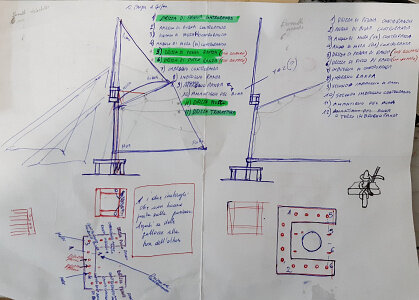
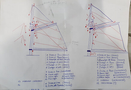
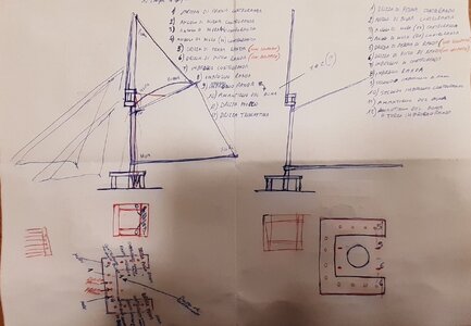
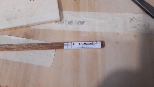
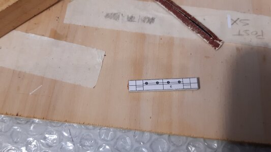
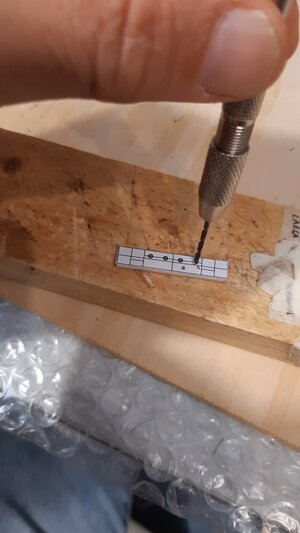
Ho inserito alcune immagini degli appunti che avevo preso per le vele e il sartiame.
Non avendo kit o disegni di riferimento, ho studiato il sistema più consono alla tipologia di vela e al periodo storico.
Le conoscenze teoriche e pratiche della vela da diporto (poche a dire il vero) non sono state di grande utilità perché le barche moderne hanno sistemi di albero e vele molto semplici.
Sono perlopiù sloop, quindi hanno un solo albero e solo due vele, la randa (tipo Bermuda o Marconi) e un "genoa" (che è un tipo di fiocco).
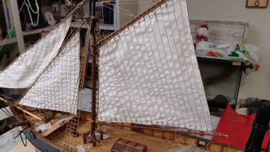
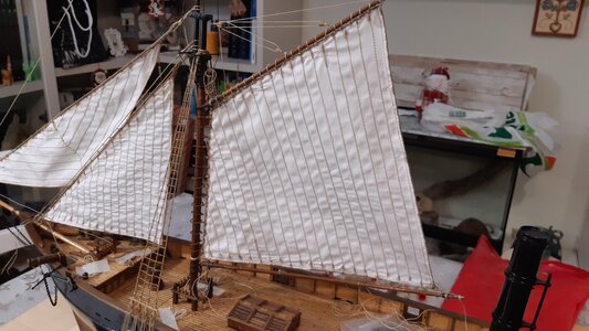
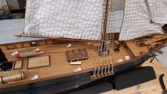
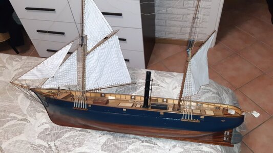
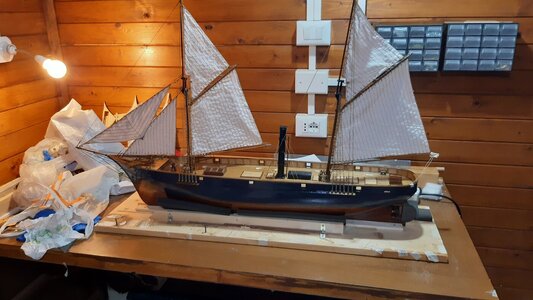
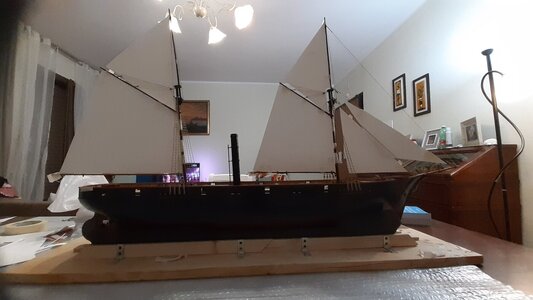
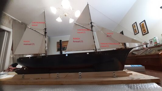
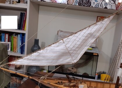
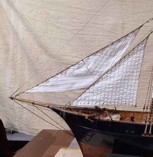
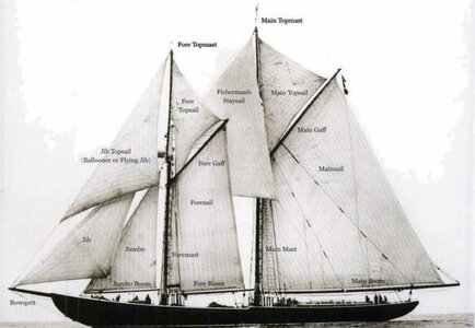
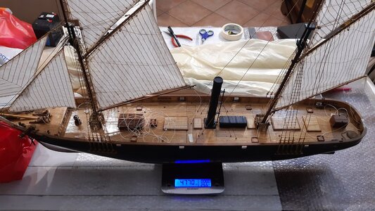
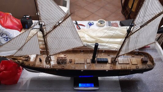
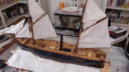
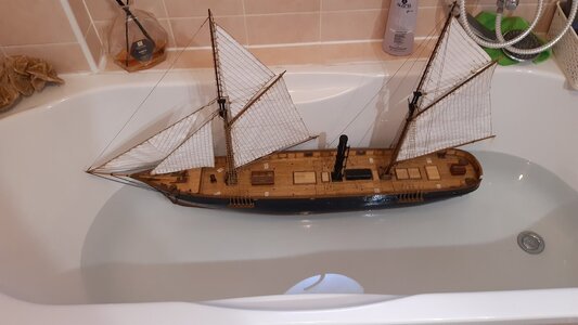
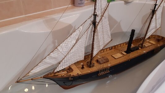
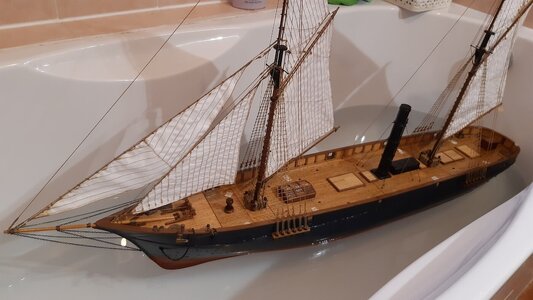
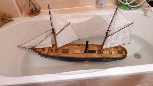
La goletta che devo completare ha tre alberi (albero di maestra, trinchetto e bompresso) e sei vele (due rande, due gaff topsails e due fiocchi).
I due fiocchi hanno nomi diversi in italiano (vela trinchetta e fiocco).
Intendiamoci, l'armo aurico (fiocchi, rande e gaff topsails), a differenza delle vele a vela quadra, è più facile da gestire, ha meno manovre e in realtà occorrono meno membri dell'equipaggio.
Inoltre è più facile da maneggiare anche per un modello RC (motivo per cui l'ho scelto all'epoca).
Tuttavia è sempre molto difficile (un gran mal di testa) dover partire da un foglio di carta bianco e iniziare a immaginare da solo tutti i dettagli.
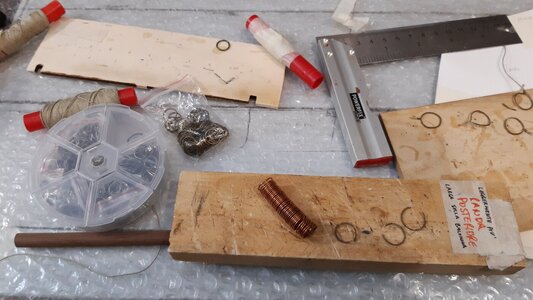
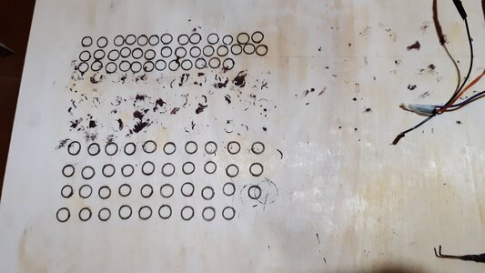
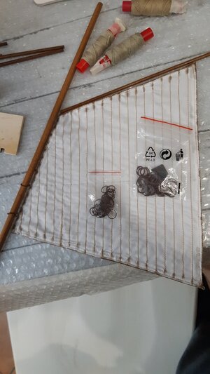
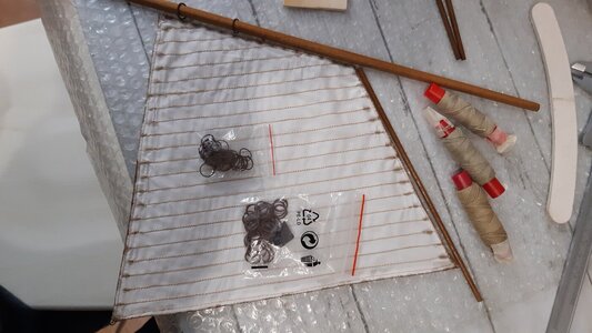
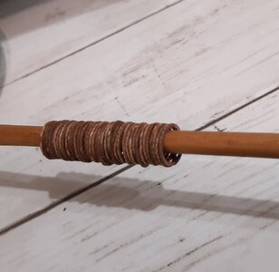
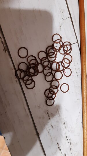
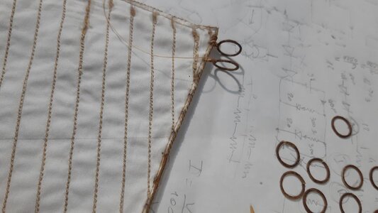
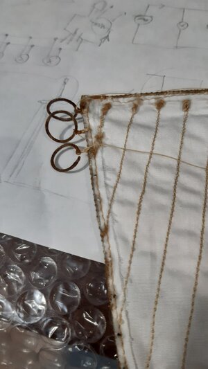
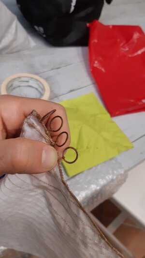
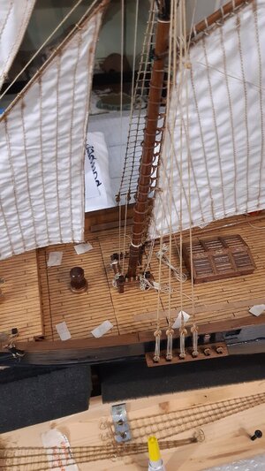
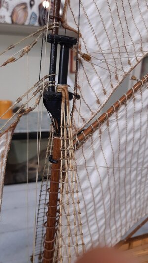
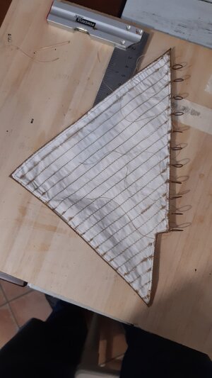
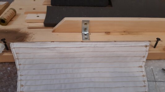
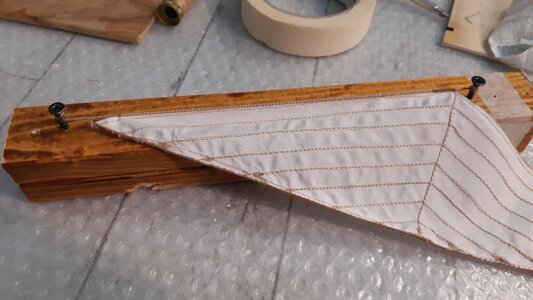
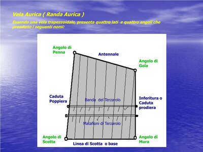
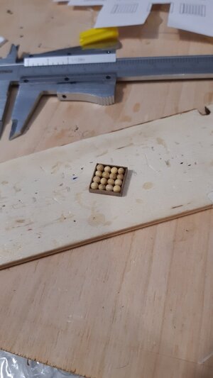
Per ammainare le rande sul lato verticale ho utilizzato degli anelli (che in italiano si chiamano “canestrelli”).
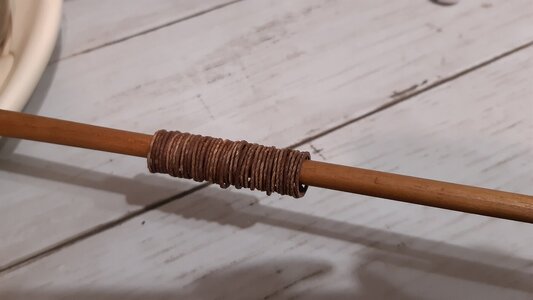
Sul picco la randa è invece legata con un particolare sistema di legatura che rimane fisso anche quando la vela è avvolta, oppure quando la randa è ammainata.
Dal lato del boma la vela non è ammainata, ma ha solo due punti di ancoraggio.
Per costruire i canestrelli ho prima effettuato alcune ricerche. Ho raccolto foto e informazioni per capire: forma, dimensioni e materiali di questi cerchi (anelli) che permettono alla randa di salire o scendere lungo l'asse principale dell'albero.
Sono essenzialmente anelli di legno, spesso ricoperti di pelle protettiva.
Inizialmente avevo pensato di realizzarli in ottone o rame, ma poi ho abbandonato questa idea perché il peso complessivo era eccessivo e posizionato troppo in alto.
Avrebbe alzato troppo il mio baricentro, ridotto la coppia raddrizzante, compromettendo la stabilità laterale della nave.
Ho pensato a varie soluzioni ma non c'erano esempi da seguire per un materiale leggero, sembra che tutti usino anelli di metallo.
Ho sperimentato un metodo insolito e molto lungo.
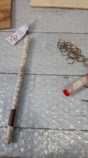
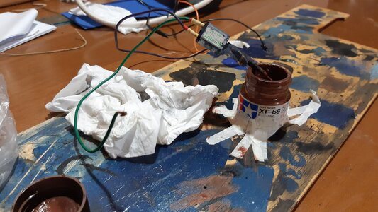
Per farla breve e non annoiarvi troppo, posso dirvi che gli anelli sono delle corde modellate e indurite con la colla e poi colorate.
Una volta terminato, li ho cuciti sulla vela.
Tenete presente che gli anelli erano aperti per essere avvolti sull'albero, quindi ho dovuto unirli tutti insieme, dopo averli posizionati correttamente.
Questa è stata l'operazione più delicata e complicata di tutte.
Sono abbastanza soddisfatto dell'opera perché sono molto resistenti e leggeri e, per la scala che ho scelto (1/60), sono sufficientemente veritieri.
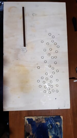
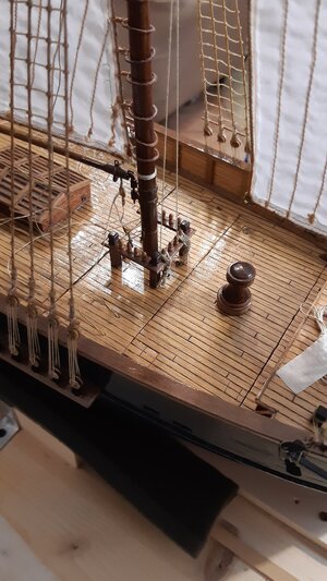
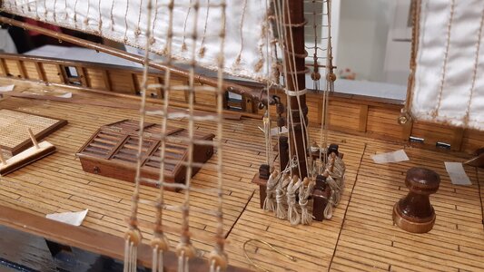
Un altro problema da risolvere è stato quello di stabilire il numero e l'entità di tutta l'attrezzatura partendo da zero e facendola arrivare su ciascuna caviglia.
Prima di ciò dovevo studiare il numero esatto delle caviglie.
Quando le caviglie non bastavano ho utilizzato le gallocce a piede d'albero.
Ogni sistema di leva (frusta, paranco, gantle, ecc. ecc.), utilizzando blocchi specifici, è stato progettato per essere funzionale e coerente con il periodo storico.
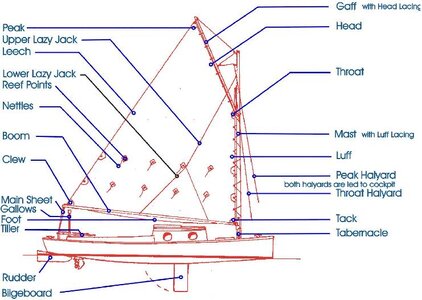
Mi sono quindi identificato con i marinai che dovevano alzare la randa, per esempio, o allacciare una vela, ma sempre confrontando immagini di navi di quel periodo.Puoi vedere la drizza del fiocco, la drizza della gola, la drizza del picco con bozzelli a uno, due o anche tre vie.
Non mi azzarderò a descrivere tutto il cordame perché è troppo difficile trovare i termini equivalenti in inglese.
Riassumendo molto brevemente (a meno che a qualcuno non interessino maggiori dettagli) posso precisare che le drizze servono per issare i picchi e vele e poi non vengono più manovrate.
Sono visibili il caricabasso e il topping lift, quest'ultimo serve a sostenere il boma quando la randa è ammainata.
Comunque se qualcuno è curioso posso rifare il disegno a mano con i termini inglesi.
Ma è un lavoro lungo quindi lo farei solo se qualcuno fosse interessato.
L'attrezzatura non è ancora completa, manca ancora qualcosina.
Good evening to all naval modelers
I inserted some images of the notes I had made for the sails and rigging.
Not having a kit or reference drawings, I studied the system most consistent with the type of sail and the historical period.
The theoretical and practical knowledge of recreational sailing (not much to be honest) has not been of great use because modern boats have very simple mast and sail systems.
They are mostly sloops, so they have only one mast and only two sails, the mainsail (such as Bermuda or Marconi) and a "genoa" (which is a type of jib).
The schooner that I have to complete has three masts (mainmast, foremast and bowsprit) and six sails (two mainsails, two gaff topsails and two jibs). The two jibs have different names in Italian (sail staysail and jib perhaps "fore stay sail" and jib).
Let's be clear, the gaff rig (jibs, mainsails and gaff topsails), unlike sails with square sails, is easier to manage, has less rigging and even in reality fewer crewmen are needed.
It is also easier to handle even for an RC model (which is why I chose it at the time).
However, it is always very difficult (a big headache) if you have to start from a blank sheet of paper and start imagining all the details on your own.
To lower the mainsails on the vertical side I used rings (which in Italian are called "canestrelli").
On the spanker the mainsail is instead tied with a particular tying system which remains fixed even when the sail is furled, or when the spanker is lowered.
On the boom side the sail is not lowered, but only has two tie-down points.
To build the baskets I first carried out some research. I have collected photos and information to understand: shape, dimensions and materials of these circles (rings) that allow the mainsail to go up or down along the main spindle of the mast.
They are essentially wooden rings, often covered in protective leather.
Initially I thought of making them in brass or copper, but then I abandoned this idea because the overall weight was excessive and positioned too high.
It would have raised my center of gravity too much, reduced the righting torque, compromising the lateral stability of the ship.
I thought of various solutions but there were no examples to follow for a lightweight material, it seems like everyone uses metal rings.
I experimented with an unusual and very long method.
To make a long story short and not bore you too much, I can tell you that the rings are strings modeled and hardened with glue and then colored.
Once done, I sewed them onto the sail.
Keep in mind that the rings were open to be wound on the mast, so I had to join them all together, after having positioned them correctly. This was the most delicate and complicated operation of all.
I am quite satisfied with the work because they are very resistant and light and, for the scale I chose (1/60), they are sufficiently truthful.
Another problem to solve was to establish the number and extent of all the rigging starting from scratch and making it arrive on each belaying pin. Before that I had to study the exact number of belaying pins. When the belaying pins were not enough I used mast foot cleats.
Each lever system (whip, tackle, gantlime, etc. etc.) using specific blocks, has been designed to be functional and consistent with the historical period. I therefore identified with the sailors who had to raise the mainsail, for example, or tie a sail, but always comparing images of ships from that period.
You can see the jib halyard, the throat halyard, peak halyard with one-two or even three-way blocks,
I won't venture to describe all the cordage because it is too difficult to find the equivalent terms in English.
To summarize very briefly (unless someone is interested in more details) I can point out that the halyards are used to pull up poles and sails and then they are no longer manoeuvred.
You can see the downhaul and the topping lift, the latter is used to support the boom when the mainsail is lowered.
However, if anyone is curious I can redo the drawing by hand with the English terms. But it's a long job so I would only do it if someone was interested.
The rigging is not yet complete, there is still a little something missing.
