17th Century Battle Station - HMS Mordaunt, 1:32 - DocBlake

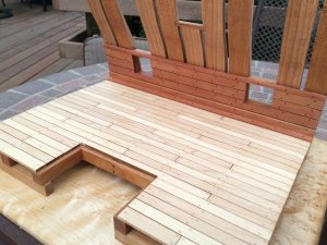
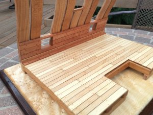
After I finished the waterway I installed the lowermost spirketing plank. It is thicker than the others and required a slight bevel to fit snugly into the angle created by the deck and the hull frames. The bulwark was planked with each plank require a bevel on both edges so that in profile they resembled parallelograms. This was because of the hull's curvature. After beveling the planks fit tight to each other and the frames. The final strake is thinner than the others and defines the lower edge of the upper deck clamp. The waterway was glued in place last. All this planking is swiss pear.Img_0192.jpgImg_0193.jpgImg_0194.jpg
 
Thanks, guys!
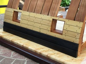
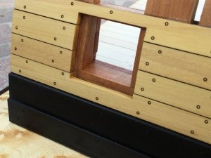
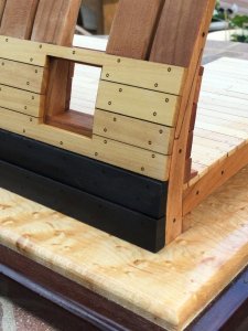
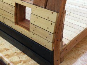
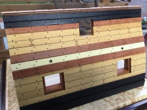
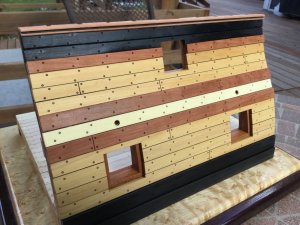
I turned my attention to the outboard planking. The model is already exceptionally rigid and once some outboard planks are added, I could probably drop it from a second story window and not damage it! The lower wale and black strake above it are ebony, measuring 1/4" and 3/16" thick respectively. The outboard planking framing the gun ports is boxwood. I included some detail shots on how the gun ports turned out and the ends of all the strakes at the exposed frames. outboard1.JPGoutboard2.JPGoutboard3.JPGoutboard4.JPG
 
Looks real sweet Dave, how did you scribe the scarf joint? A real nice touch

G'day Don
You are very observant, there were so much brilliant work that Dave did, I didn't noticed it.
Nice touch Dave! What I've done in the past when doing a false scarf joint was to lightly 'colour-in' a darker or lighter, watercolor pencil over one section, and use a touch if water so the colour will soak into the wood. The result is, there is a minor change in the colour of the frames where they join.
Just a thought!
Havagooday to all
Greg
 
Thanks, guys!

I just carefully drew the scarf on the wood and used a curved #20 blade to carefully score the scarf lines. Then I flipped the blade over and dragged the back of the blade point through the lines to widen them. A mechanical pencil with a 0.1mm lead provided the caulking!
 
Thanks, Mike!
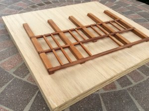
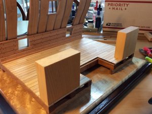
I glued the main deck beams and carlings together in my new steel squaring jig. Because the ledges were cut to size to fit the mortises in the carlings perfectly, sanding the char from the pieces made the fit too lax. i just cut some cherry stock, milled it to the proper thickness, and cut my own ledges that I custom fit to the deck and glued in place. The lodging knees, hanging knees and the remainder of the ledges outboard will be fitted later. Next up: Shaping and fitting the upper deck clamp.
maindeck2 (1).JPGmaindeck2 (2).JPG
 
Just outstanding Dave!!! I was stressing that I hadn't cut you new ledges yet!! It seems sad to cover most of that with planking.. it just looks fabulous!! Ok, I am going to tackle those lodging knees next!
 
G'day Dave
I havta echoe Mike's statement...great and neat job.
Could you show us your new steel squaring jig please. Just curious mate.
Happymodeling
Greg
 
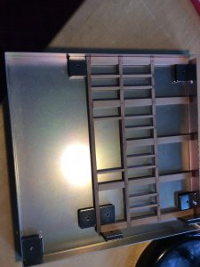
Greg: The squaring jig is simply a steel square qith the edges turned up perpendicular to the base. Objects are held in place by magnets. I included a shot of the deck framing in the jig!

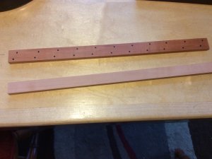
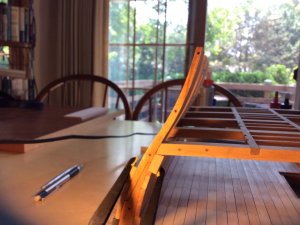
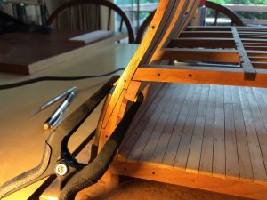
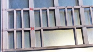
I started work on the upper deck clamp. As in Mike's build, the lower edge of the clamp was fine, sitting squarely on the spirketing. The lower edge of the deck beams must be 2-1/4" above the lower deck surface. This is important so that the upper bulwark planking turns out correctly. The first thing I did was cut two blocks out of scrap, exactly 2-1/4" tall. These would be double sided taped to the lower deck and support the inboard end of the deck beams at that proper height. When I started to fit the upper deck clamp, and I ran into a problem. When Mike fit his, he had to cut a little of the top of the clamp at an angle to accommodate the beams, and reach the "magic number" of 2-1/4". In my case, the beam sat on the clamp right at that number but there was no excess to cut on an angle to accommodate the beam resting on it. I needed a wider (taller) deck clamp. I determined that 17 degrees was the proper angle for my model, and cut an oversized deck clamp. I then cut it the the right height by "sneaking up" on the final measurement using my Byrnes saw and carbide blade. The "magic number" is now there, but the clamp is about 3/32" taller than it should be. Hopefully no one will notice! Also, the angle the clamp is cut to would probably be better at 18 degrees, but I'm just leaving it! Check the photos! I also drilled holes and placed the simulated bolts that held the clamp in place.IMG_0207.JPGIMG_0204.JPGIMG_0203.JPGIMG_0202.JPGIMG_0205.JPGIMG_0206.JPG
 
I have to ask you (or better all three of you) one question about your deck construction:

I used one of your last photos

IMG_0207.JPG

I realized, that your carlings are cutting the deck beams over the complete width of the beam.
Should it not be in such a way, that the beams are only notched to take over the ends of the carlings, like i tried to show with my red lines?
So it is only a smaller part for bedding the carlings - like you did it for the bedding of the ledges in notches of your carlings......
I do not know, if this was laready discussed or mentioned from your side(s) before...
 
Hi Uwe!
The three of us have been having an ongoing discussion about the framing of the upper deck. It is NOT historically accurate. The design is very stylized, and changes were made to accommodate the gunports - things you’d not see on a real ship. Also, when Jeff drew the plans he wanted to simplify construction so a novice or intermediate builder could complete the model. Your points are well taken!
 
The three of us have been having an ongoing discussion about the framing of the upper deck. It is NOT historically accurate. The design is very stylized,

when I built the prototype of the kit for Model Ship Builder I realized the entire model is "stylized" and not historical correct.
it is a nice model and you guys are doing a fantastic job so for this model historical correctness is out the window and I don't think it matters.

the original practicum is at 3/8 = I foot scale in the practicum appendix A pg 29 the deck planking is listed as 3/32 x 3/8 that is way out of scale it makes the width of the deck plank 12 inches 7 inch was the max for deck plank average 5 inches wide is the norm. drawing 1 is what Jeff drew drawing 2 is the max width for a plank and the last drawing is what a cross section of a deck plank looks like. The rule of thumb is the thickness is about 1/2 the width. Wood if cut to wide and to thin it tends to cup so decking was closer to square in cross section.

but like I said Dave it is really a good looking model love the Maple base and the fine workmanship.
historically correct or not who really cares? it looks good

decking.JPG
 
A little more progress!

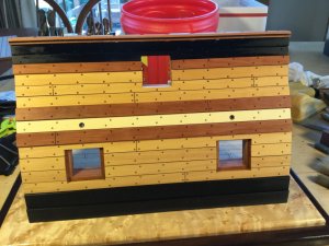
I glued the remaining half frames above the gun ports into place and worked on planking the exterior. The two channel wales and the great rail are swiss pear and the strake between them was supplied in both boxwood and holly. I chose the holly. The wale, black strake and two sheer strakes are ebony. The remainder of the outboard planking is boxwood. There will be a rosewood gunwale at the top of the bulwark. There were pre-drilled holes for the gun port lid control lines, but these had to be drilled through the framing to emerge just above the upper deck clamp's upper edge. With that done I completed the planking up to the sheer trim. The piece of trim was provided with either a double bead or triple bead design. I haven't decided which to use yet. Work turns to the upper deck next as we fit the support columns, knees and remaining ledges.

I enclosed photos made indoors with incandescent light as well as outdoors in daylight. Amazing how different the colors appear! outplank1.JPGoutplank2.JPGoutplank3.JPGoutplank4.JPG
 
Back
Top