1930 Bentley Blower by Aifix 1/12 build log [COMPLETED BUILD]

Interesting arrangement with the bevel gears from crankshaft to camshaft. Timing adjustment looks like it would not be very precise, but hard to tell from just this image. I assume the gears on the vertical shaft would have to be bolted on each end with a key, or at least one end, otherwise it couldn’t be assembled? Also it looks like there is no provision for bearings?
Looks cool though. ;)
 
Last edited:
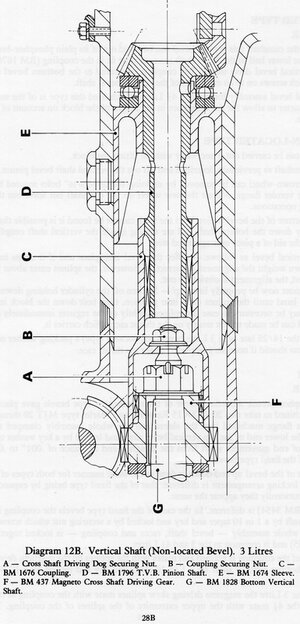
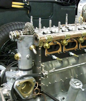
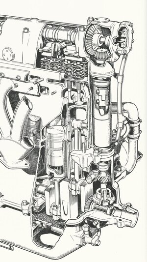
As bizarre a design as it seems, it's actually how it was. There was a vertical shaft mounted in the front tube with a bevel gear combo at the top driving the camshaft and another at the bottom (G) taking power from the crank. Timing was probably done at the large bevel gear mounted on the camshaft. There was a intermediate helical gear set (F) to drive the magneto. bentley-vertical-shaft-1_orig.jpgAs for bearings and other bits, I didn't bother since most of this will not be visible and at 1/12 scale, would be lost anyway. And remember that all of this has to fit inside the Airfix moulded plastic engine block.Bentley_'3_litre'_Bentley_engine_overhead_valve_gear_(Modern_Motors,_I)_016.jpg9a728f0c7a35ff9c41f01ca76d678a48.jpg

Here is how Bugatti did the same camshaft drive designbugattibresciaengine.jpg
 
As bizarre a design as it seems, it's actually how it was. There was a vertical shaft mounted in the front tube with a bevel gear combo at the top driving the camshaft and another at the bottom (G) taking power from the crank. Timing was probably done at the large bevel gear mounted on the camshaft. There was a intermediate helical gear set (F) to drive the magneto. View attachment 379413As for bearings and other bits, I didn't bother since most of this will not be visible and at 1/12 scale, would be lost anyway. And remember that all of this has to fit inside the Airfix moulded plastic engine block.View attachment 379410View attachment 379411

Here is how Bugatti did the same camshaft drive designView attachment 379414
Interesting, thanks for the reference material, this helps. I see they had an upper and lower shaft that are coupled with a spline (upper D, lower C & G assy), with a thrust bearing on the top shaft.
At scale, what you have modeled is probably close enough. ;) And I agree it looks like the timing would have to be adjusted on the cam gear...possibly the reason for the castle nut?
 
Last edited:
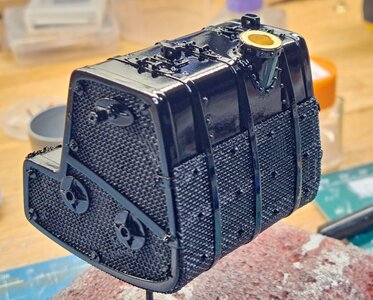
Hi everyone, I 've been quite busy. The fuel tank is done and painted, ready for final assy.20230620_170706.jpg
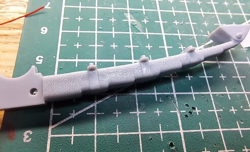
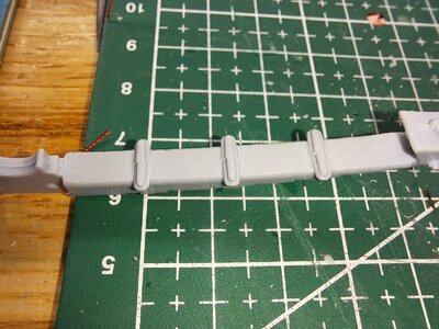
Next I detailed the 4 leaf springs. What the kit provides is rather basic, the ubolt are just about non existing and the rope wrapping in moulded in so not very convincing. This is what they look like.20230614_204926.jpg20230614_205101.jpg
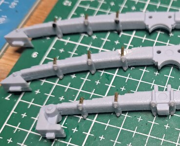
I made a batch of ubolts, and added 2 nuts per ubolts, much more realistic.20230616_214604.jpg20230617_101113.jpg
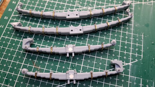
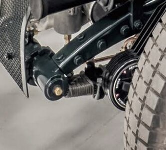
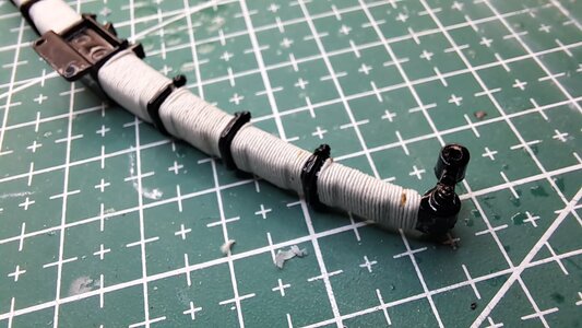
I then rope wrapped all 4 leaf spring. This is actually how it was done back then. Screenshot_20230614_220603_Photos.jpg20230618_213850.jpg
20230619_214345.jpg
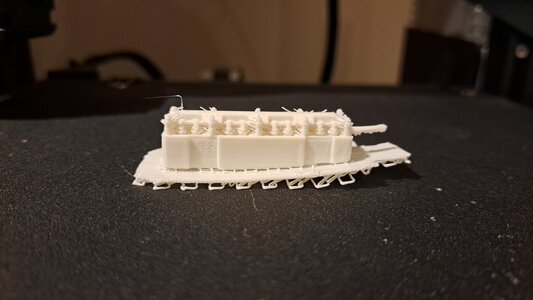
So next up, I'm undertaking the rear brakes. But firts, a little side note. Last sunday, I received a 3d filament printer as a father's day gift. The printer is used and not worth much but I figured l'd give it a try. The first thing I printed was the engine head.20230618_220726.jpg
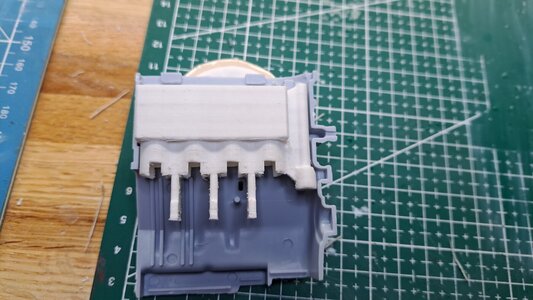
Not so good. Then I tried the engine bloc 20230619_214544.jpg
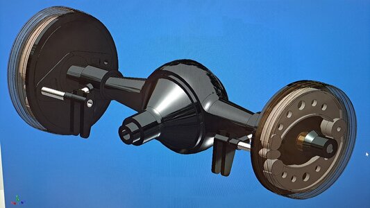
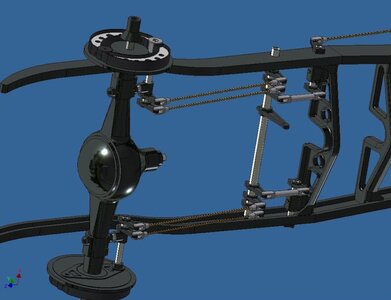
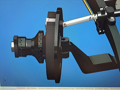
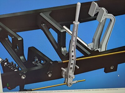
Much better but still not precise enough. These kind of parts really need a resin printer. So I figured I'd try again but with a much simpler design. That's where the rear brakes come in. My original goal was to have working brake linkage, like on the Alfa. But I decided to go much further and redo the whole system. So I first 3d modeled the rear end and added new brake shoes, shoe mounting plate, shoe cam with it's pivot shaft actuating lever ans mounting bracket.
The 3d model20230620_163956.jpg
View attachment 20230620_154131.mp4

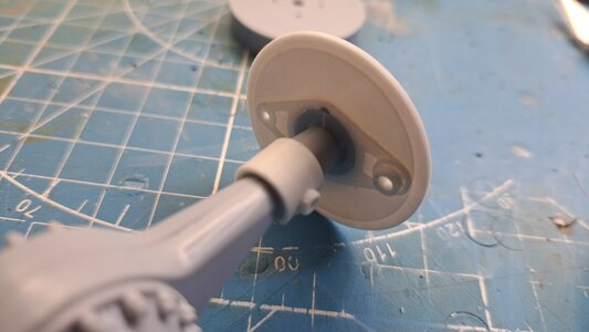
Here's what the kit provides in termes of shoe and mounting plate 20230620_215620.jpg

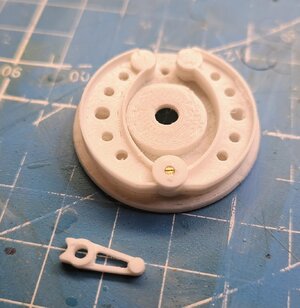
my first try at the shoes and mounting plate 20230621_170815.jpg

The kit's mounting plate 20230620_215747.jpg
My detailed shoe mounting plate and cam mounting bracket 20230621_170635.jpg
My conclusion is that not only will I have I working linkage, I should also have working brakes. Pretty cool !
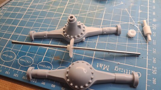
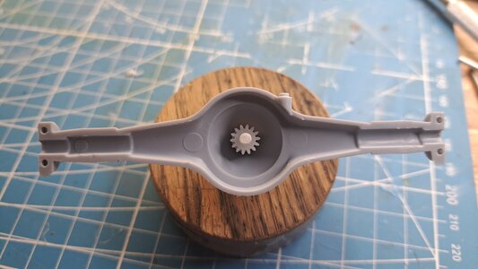
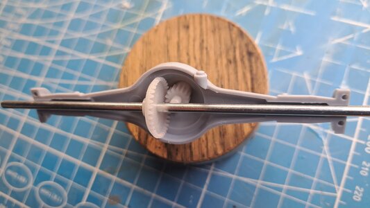
Then the mecanical nerd in me had an idea, what if I could drive the wheels from the crank shaft I'll be adding. Some of you may know that this kit once had an electric motor somewhere to drive the wheels. The motor is long gone from the kit but certain features remain such as a square ended drive shaft the goes from the differentiel all the way to the engine, even goes thru the transmission. So all I ad to do was to install 2 gears inside the differentiel case, print a square end jack shaft that goes from the drive shaft to the pinion gear and voila, not a real differentiel but close enough.
The componants 20230621_170243.jpg
Pinion installed 20230621_170355.jpg
Axel and crown gear20230621_170450.jpg
And it works ! How nerdy is that?
 
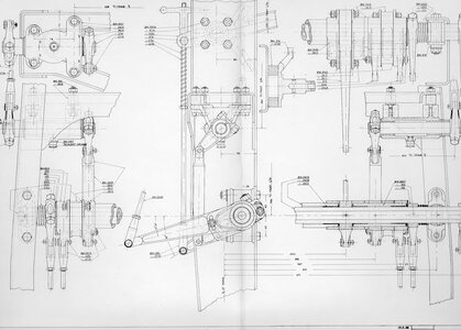
Did some more work on the brake system. I'm trying to figure out the linkage configuration which is not easy considering the enormous lack of detail on the airfix kit and the lack of info on the web. I did find a drawing that shows a portion of it. bentley-compensator_orig.jpg
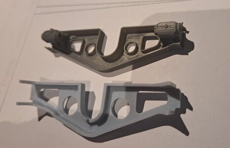
I reprinted certain parts in ABS which is sandable compared to PLA. It's not the final version but I'm getting there.
View attachment 20230625_210732~2.mp4

20230625_210621.jpg
I'm also redoing the kit's cross members to add certain details like the front brake transfer pivot points. Again, not final.
20230625_211614.jpg
The modeling of the complete brake system is slowly advancing.
Capture d’écran 2023-06-26 215140.jpg
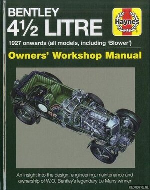
I ordered the Haynes Bentley Blower shop manuel which should give me some info.
1286562377.0.l.jpg
 
Hi François. Catching up your build and flabbergasted about the amount of details. Just GREAT.
Last week during my bike holiday in Scotland a Blower Bentley was passing. What a sound! Much more impressive than my BMW 6-cilinder.
Regards, Peter
 
Thank you Peter. Wow, you're lucky ! I'd really like to see one live but unfortunately, they aren't any Blowers in Québec. I'll have to make due with what I find on the net. This kit really shows it's age, the moulds are over 50 year old. A lot of flash, a lot of pin marks and not much details. But, it gives me the opportunity to refine my skills.
 
To remove the kit chrome- it's really aluminum-spray the parts tree with caustic oven cleaner and leave it in a ziploc bag overnight. The chrome should wash right off- use a toothbrush on any stubborn bits or let it sit in the bag a little longer. It won't harm the plastic. It looks like Easy Off is available in Canada- that's what I have used in the past.
 
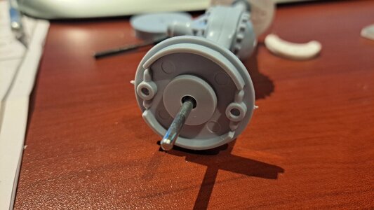
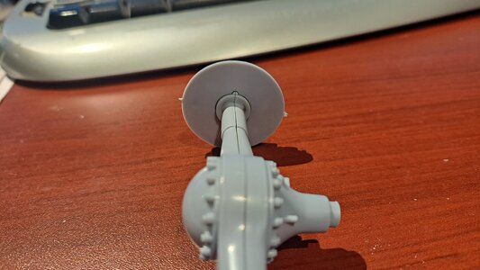
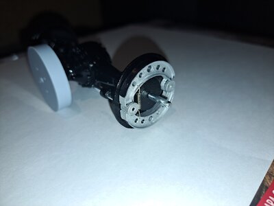
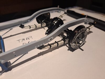
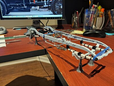
The rear axel is assembled and the brake shoes are working better with the new cam design.
20230628_215648.jpg20230628_215528.jpg

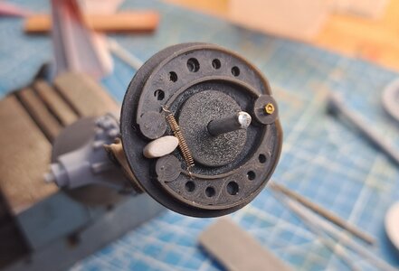
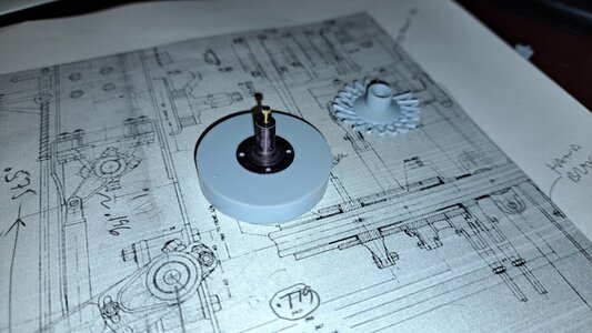
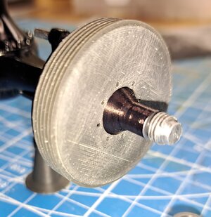
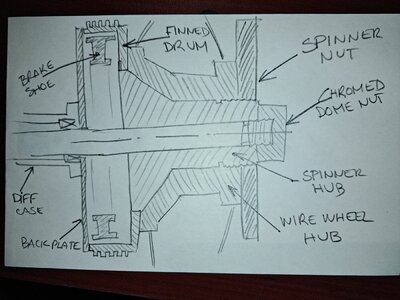
Now, I'm toying with the idea of printing new finned drums with proper spinner hubs.
image~2.jpg
Here is my firts test for the hub
20230628_070030.jpg
The brake system's cad model is advancing nicely. I added the brake pedal. Unfortunately, I tried printing à few levers but they're too small for a filament printer, l'll have them resin printed.
View attachment 20230628_215117.mp4
 
To remove the kit chrome- it's really aluminum-spray the parts tree with caustic oven cleaner and leave it in a ziploc bag overnight. The chrome should wash right off- use a toothbrush on any stubborn bits or let it sit in the bag a little longer. It won't harm the plastic. It looks like Easy Off is available in Canada- that's what I have used in the past.
I've reread your post. My parts are real plated chrome with the brass or copper or whatever it is under plating. This stuff is really hard. I'll try zyploc trick but I have serions doughts. I'll probably end up printing these parts.
 
Hey Francois, looks like you’re making some good progress!
I have contemplated getting a resin printer, but fear if I started modeling and printing parts on a regular basis, that I would end up making my own kit from scratch! ROTF At which point there is no return, because making the CAD models is as much fun as building a model to me. I have already made CAD models and had parts printed for some of my ship and airplane builds. But I am always thinking about making a car or motorcycle from scratch and printing all the parts myself.

Anyway, I like what you are doing, keep up the good work.
 
Yeah Dean, I know what you mean, I always said that I wanted to fabricate my parts by hand but now that I've had a taste on 3d print, I can't stop!! Espacialy since I do my own designing. Oh well, assembling moulded partsbor printed parts, not much difference except for the result, and the fun!!
 
The Airfix plating on that kit seems to be famously intractable! Someone used ferric chloride- standard printed circuit etchant:
Another board mentions some European products- the SDS/Safety data sheet should be easy to find to see what the active principal is-
Keep on trying!
 
Last edited:
I'm almost done with the brake system modeling. I thought the italiens where gutsy designers, but the way these bentley boys did the front braking system is beyond cool! They use double universal joints with the pivot points properly located to permit both an up/dw mouvement of the wheel while still being able to steer. Quite a nice design. 20230701_221711.jpg
View attachment 20230701_221945.mp4

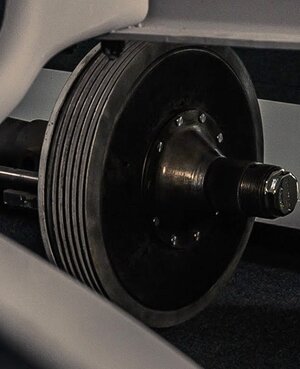
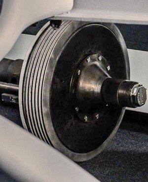
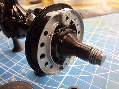
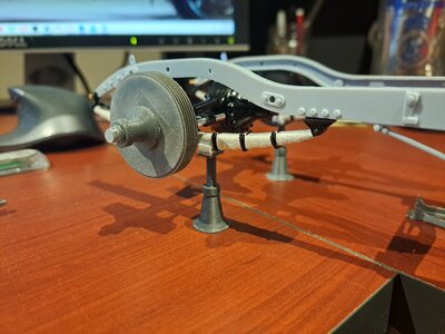
I also printed the rear drums and spinner hubs. This is what it's based on.image~3.jpg
And my version (not final)
20230630_212132.jpg
20230630_212028.jpg

I started modeling the handbrake system, and if all goes to plan, it should be functional20230701_222029.jpg

And finally, I printed some small ajustable candles, I wanted to see if I could print functionning threads, and it's possible20230701_222802.jpg20230701_222816.jpg

20230630_213934.jpg
 
Bought the Haynes book at cheepo price online. Thanks for the heads up.
 
reading your posts and watching your work - I am every time newly surprised what is possible
 
Back
Top