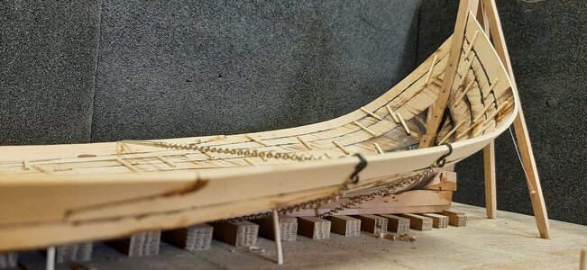
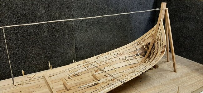
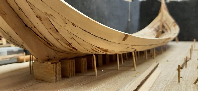
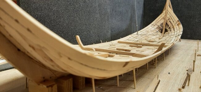
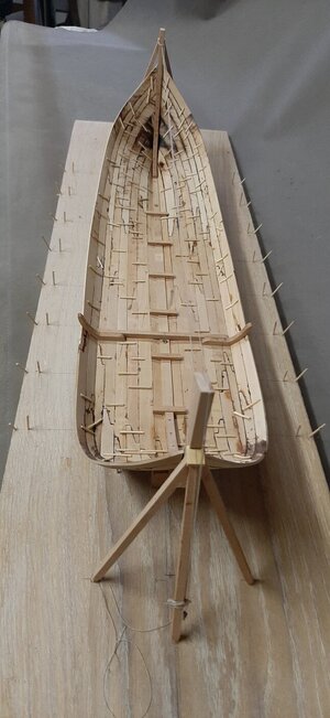
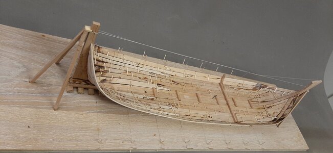
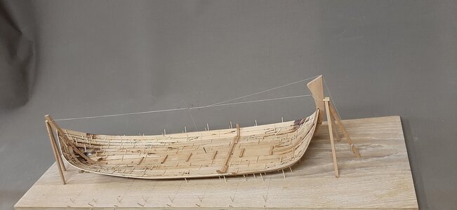
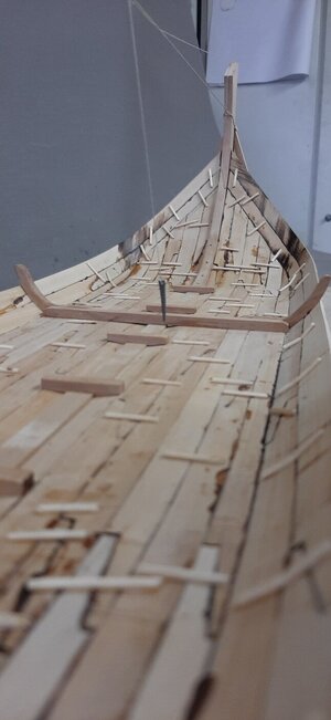
Hi @Bela
Based on the stern frame shape as proposed by Van Yk in his book on page 77 as pointed out to me by Ab Hoving.
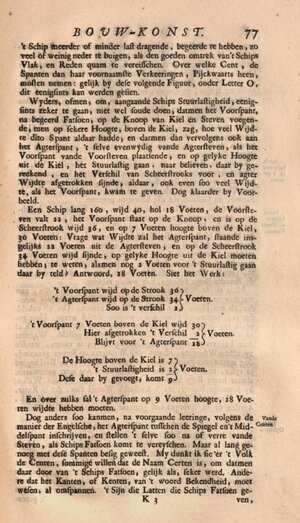
There should be a balance between the volume in the fwd part of the ship compared to the stern, if this balance in bouyancy is not there you should ballast the ship to trim.
Van Yk mentions the following regarding the shape of the bow frame shape vs the stern frame shape. Creating the same width of the fwd frame and stern frame at a height of 7 feet from the keel.
I have recalculated this for the ghost ship as follows:
In itself Van Yk is very simple, but it is unclear to me where Van Yk gets that 7 feet above the keel from, this must have a relationship to the depth, since this also partly determines the height of the “scheerstrook”.
His example shows a depth of 18 feet and he measures 7 feet from the keel at the fwd frame.
On the Ghost ship the depth is 9 feet and 3 inches, so I would have to measure 9.27/18 x 7 = 3.6 feet or 3 feet 7 inches = +/- 1 meter above the keel.
Here I have placed an extra waterline at a height of 1 meter + keel thickness + steering load = 1 + 0.296 + 0.48 = 1.77 mtr
He adds the “stuurlast” (trim) for the stern frame, the strange thing is that the full stuurlast is measured at the end of the keel and not on the stern frame, which sinks less because it is placed further forward in the ship, so this measurement is fore and aft. not in 1 waterline.
I have done the same here as Yk, so I am going to add the full trim load to the measurement, the 3 feet and 7 inches is then increased by 1 foot and 8 inches of stuurlast, or 5 feet 5 inches = 1.544 meters, here I have to add again the thickness of keel and stuurlast at the stern frame.
Length of keel is +/- 22.2 m, stern is at a distance of stem rake from the stern which is 4.5 m, ratio is 0.2 x stuurlast.
Measuring height in the stern is then 1.544 + 0.296 (keel) + (0.2 x 0.48 (steering load on stern)) = 1.94 m. This is where the stern frame waterline comes in.
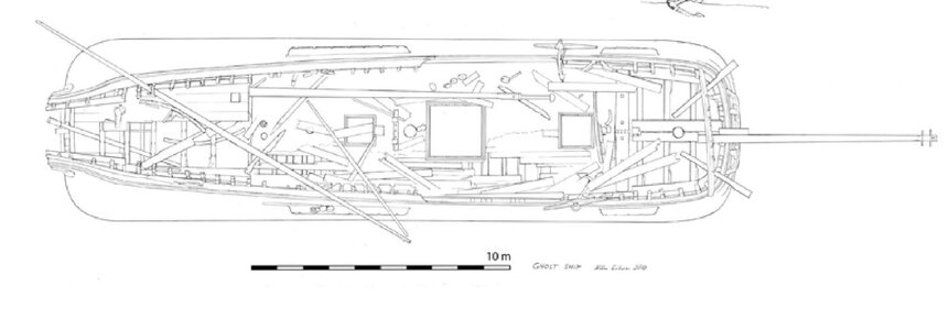
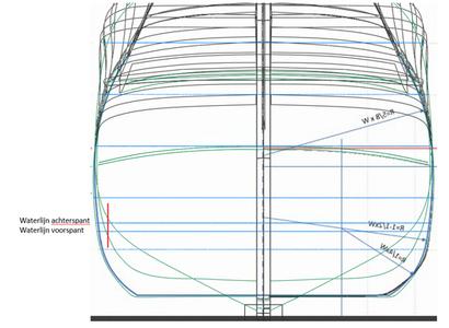
The waterlines 1.777 m and 1.94 m have now been drawn, as well as the frame at 4.5 m (stern frame), 17.8 m centre frame and 22.2 m fwd frame.
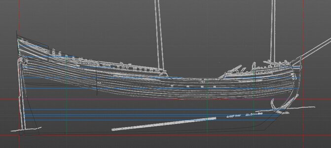
The width at the fwd frame calculated waterline now should be equal to the stern frame width at the calculated waterline, this as the ghost ship has the same overall width at the fwd frame as at the sternframe due to its straight top view of the scheerstrook.
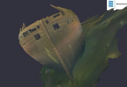
The old frame you see below:
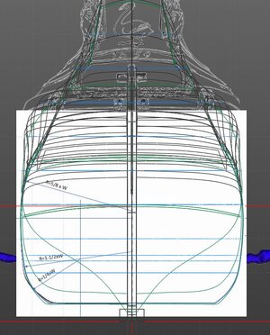
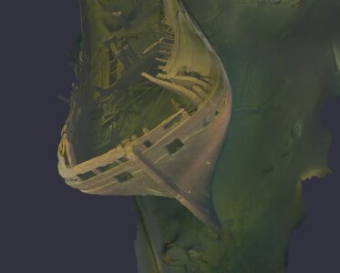
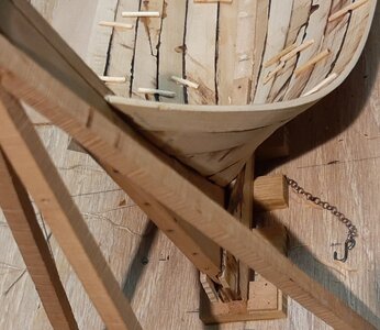
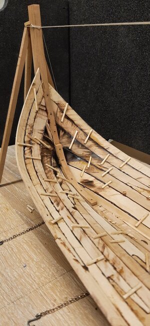
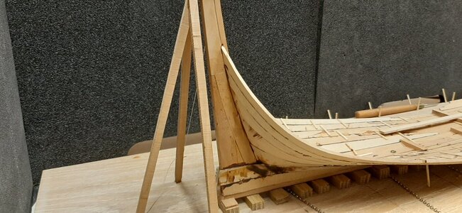
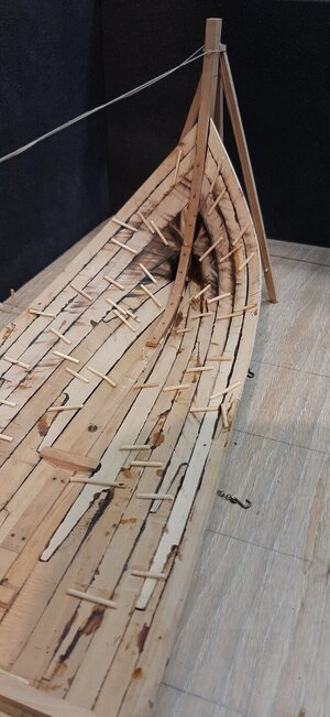
The new frame based on the Van Yk set up is as below, based on the same width at the calculated waterline.
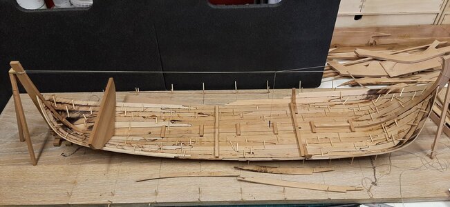
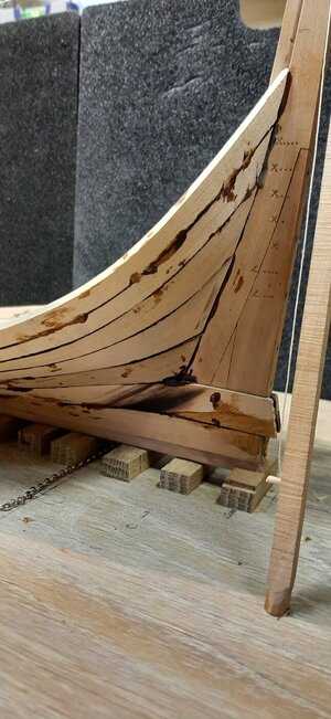
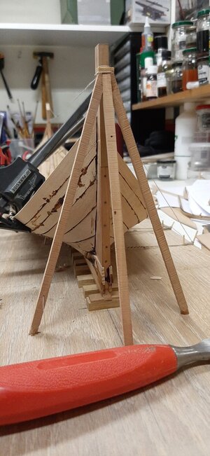
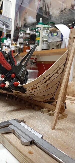
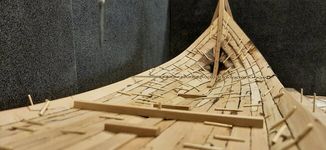
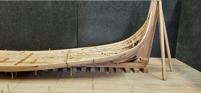
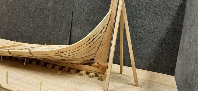
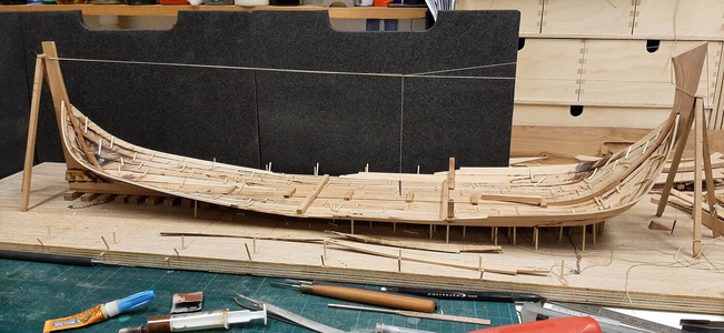
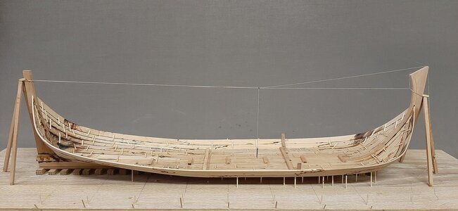
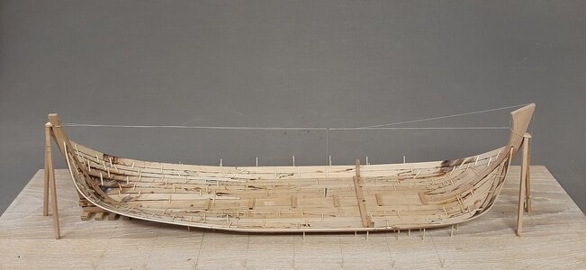
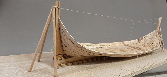
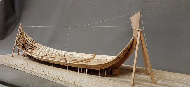
The rest of the stern is shaped by the flow of the planks.
I am also curious to see the finall shape evolving, in the end this is an experiment for me.
Based on the stern frame shape as proposed by Van Yk in his book on page 77 as pointed out to me by Ab Hoving.

There should be a balance between the volume in the fwd part of the ship compared to the stern, if this balance in bouyancy is not there you should ballast the ship to trim.
Van Yk mentions the following regarding the shape of the bow frame shape vs the stern frame shape. Creating the same width of the fwd frame and stern frame at a height of 7 feet from the keel.
I have recalculated this for the ghost ship as follows:
In itself Van Yk is very simple, but it is unclear to me where Van Yk gets that 7 feet above the keel from, this must have a relationship to the depth, since this also partly determines the height of the “scheerstrook”.
His example shows a depth of 18 feet and he measures 7 feet from the keel at the fwd frame.
On the Ghost ship the depth is 9 feet and 3 inches, so I would have to measure 9.27/18 x 7 = 3.6 feet or 3 feet 7 inches = +/- 1 meter above the keel.
Here I have placed an extra waterline at a height of 1 meter + keel thickness + steering load = 1 + 0.296 + 0.48 = 1.77 mtr
He adds the “stuurlast” (trim) for the stern frame, the strange thing is that the full stuurlast is measured at the end of the keel and not on the stern frame, which sinks less because it is placed further forward in the ship, so this measurement is fore and aft. not in 1 waterline.
I have done the same here as Yk, so I am going to add the full trim load to the measurement, the 3 feet and 7 inches is then increased by 1 foot and 8 inches of stuurlast, or 5 feet 5 inches = 1.544 meters, here I have to add again the thickness of keel and stuurlast at the stern frame.
Length of keel is +/- 22.2 m, stern is at a distance of stem rake from the stern which is 4.5 m, ratio is 0.2 x stuurlast.
Measuring height in the stern is then 1.544 + 0.296 (keel) + (0.2 x 0.48 (steering load on stern)) = 1.94 m. This is where the stern frame waterline comes in.
The waterlines 1.777 m and 1.94 m have now been drawn, as well as the frame at 4.5 m (stern frame), 17.8 m centre frame and 22.2 m fwd frame.

The width at the fwd frame calculated waterline now should be equal to the stern frame width at the calculated waterline, this as the ghost ship has the same overall width at the fwd frame as at the sternframe due to its straight top view of the scheerstrook.
The old frame you see below:

The new frame based on the Van Yk set up is as below, based on the same width at the calculated waterline.

The rest of the stern is shaped by the flow of the planks.
I am also curious to see the finall shape evolving, in the end this is an experiment for me.


