-

Win a Free Custom Engraved Brass Coin!!!
As a way to introduce our brass coins to the community, we will raffle off a free coin during the month of August. Follow link ABOVE for instructions for entering.
-

PRE-ORDER SHIPS IN SCALE TODAY!
The beloved Ships in Scale Magazine is back and charting a new course for 2026!
Discover new skills, new techniques, and new inspirations in every issue.
NOTE THAT OUR FIRST ISSUE WILL BE JAN/FEB 2026
You are using an out of date browser. It may not display this or other websites correctly.
You should upgrade or use an alternative browser.
You should upgrade or use an alternative browser.
A Dutch Fluyt in shell first, reconstructing the "Ghost ship" scale 1:36
- Thread starter Maarten
- Start date
- Watchers 74
-
- Tags
- dutch fluit
80% of the first layer whereas the second layer has double the number of treenails. So 80/300=26,667%I seen a wreckage of a Dutch ship and I think you are just halfway nailing (not 80%). So keep up the good work my friend.

And after that also the sides will follow.
The first treenailing of the liggers and zitters to the shell is finished.
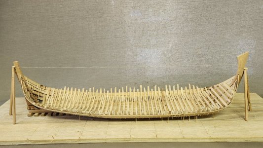
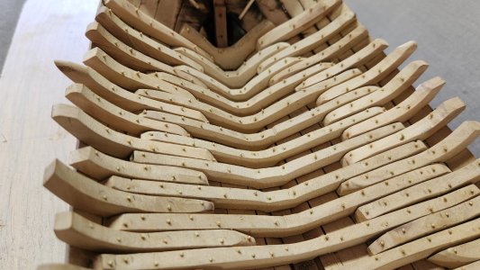
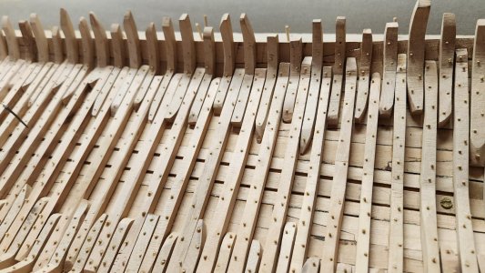
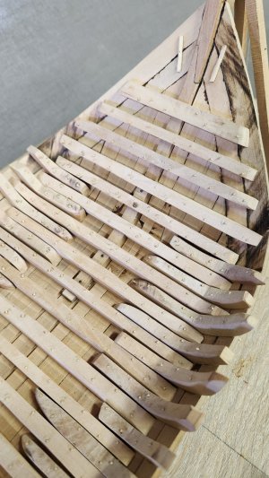
All these treenails are drilled allway through the construction and were wedges and pegged on the in and outside.
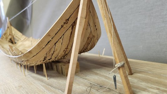
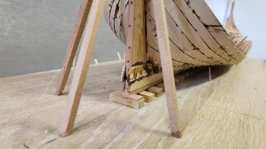
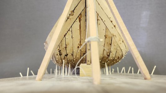
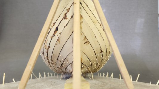
Next step is sanding the inside and prepare for the keelsom or in Dutch zaathout.
Fist repid sanding is with a rotary Proxxon sanding disk, ideal tool for the job.
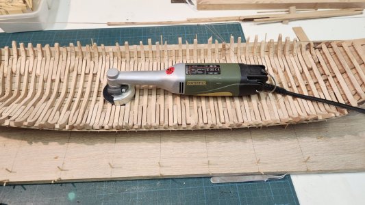
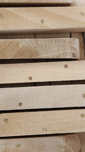
Very smooth after sanding and the treenails a nicely visible allthough the ceiling will be fitted over them.
Next time nailing the liggers to the kiel.


All these treenails are drilled allway through the construction and were wedges and pegged on the in and outside.


Next step is sanding the inside and prepare for the keelsom or in Dutch zaathout.
Fist repid sanding is with a rotary Proxxon sanding disk, ideal tool for the job.

Very smooth after sanding and the treenails a nicely visible allthough the ceiling will be fitted over them.

Next time nailing the liggers to the kiel.
A nice outcome of the treenails, Maarten. About not visible later: “Luckily, we still have the photos.”. And because of this post: we also know!The first treenailing of the liggers and zitters to the shell is finished.
View attachment 472116View attachment 472117View attachment 472118View attachment 472119
All these treenails are drilled allway through the construction and were wedges and pegged on the in and outside.
View attachment 472120View attachment 472121View attachment 472122View attachment 472123
Next step is sanding the inside and prepare for the keelsom or in Dutch zaathout.
Fist repid sanding is with a rotary Proxxon sanding disk, ideal tool for the job.
View attachment 472124
Very smooth after sanding and the treenails a nicely visible allthough the ceiling will be fitted over them.
View attachment 472125
Next time nailing the liggers to the kiel.
Regards, Peter
we know everything.... we also know!
amazing work
this is the only model in our forum, where you can say every day - my model / diorama is now completed
Very beautiful nailing, absolutely great
It looks great, Martin and I wish you lots of fun, great conversations and reasonably good weather, greetings to Holland.
Many thx Tobias, I will certainly doIt looks great, Martin and I wish you lots of fun, great conversations and reasonably good weather, greetings to Holland.

After a great meeting in Amsterdam it was back into the workshop and work on the keelsom.
The size of the keelsom I have taken from the E81 Samuel wreck, which is with 95 Amsterdam foot the same lenght as my fluyt ship.
The keelsom width is 1 3/4 ft and a thickness of 2/3 ft.
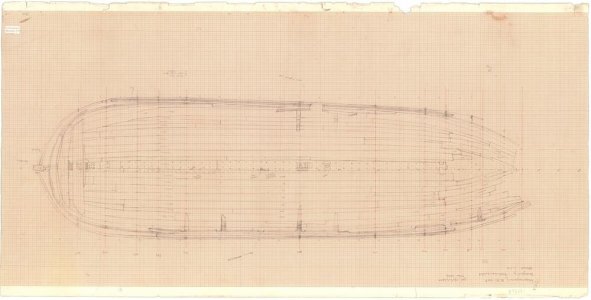
It is composed of three parts, the aft part which is largest and contains two holes which are to my opinion for the pumps and the main mast foot. It connects via a scarph joint to the middle part and the curved bow piece.
See below the archeological drawing of these.

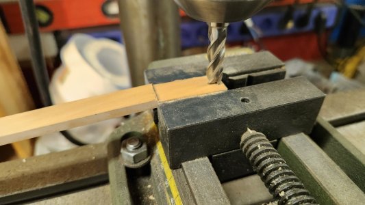
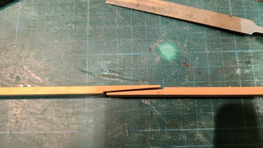
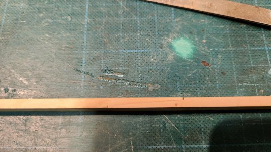
After preparing proper size strips the scarph joints are milled.
Until a proper fit is created.
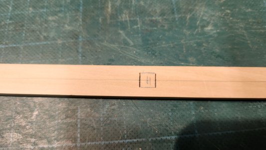
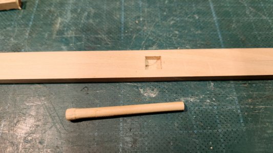
In the long aft piece a mast step is created, it is situated in the center of the ship half way between bow and stern.
I have used again the E81 as an example.
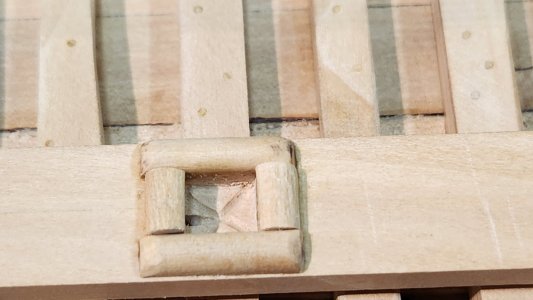
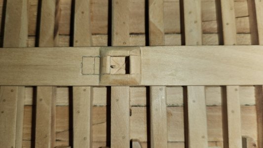
And the original on Samuel.
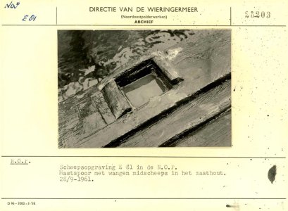
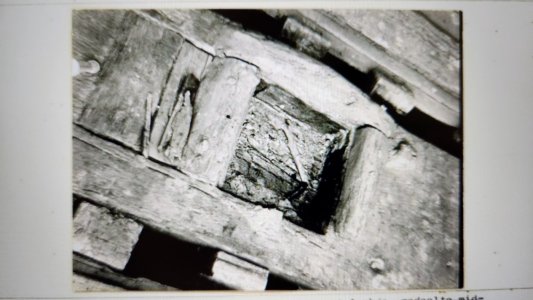
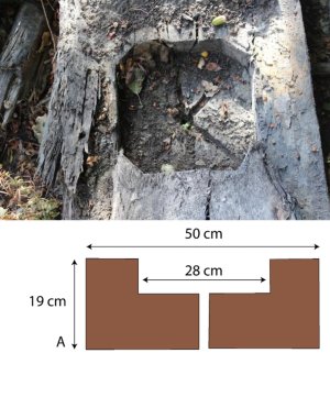
At the bottom I have created a drain to avoid rot to the mast and keelsom. I have taken this from another wreck, the K47-II which was a freighter between 30-35 mtr from early 1700. It's zaathout is very comparable in size. See below the maststep picture from the archeological report of this wreck which is in a farm field in the Noord Oost polder., yes here in the Netherlands there are quite some shipwrecks in fields which were previously sea bottom
A next study was on the fastening of the construction.
I expected before the zaathout (keelsom) was fitted the liggers (floors) would be fixed to the keel. I had misinterpretated the paper "double dutch solutions in flush planked shipbuilding" of Thijs Maarleveld about the SO 1 wreck where he states

The liggers were only nailed on the edges to the planking for temporary fitting. Then they were treenailed to the planks, so still no fixing to the keel.
Only after fitting the zaathout bolts were driven into the construction.
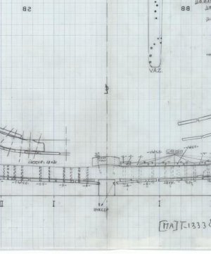
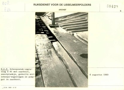
See below again a picture of E81 here the zaathout, ligger and keel are shown with two bolts attaching the zaathout to the ligger. There seems to be no connection between ligger and keel which looks odd to me as this really weakens the construction.
Maarleveld writes in his SO 1 paper

This means minimum 1 bolt in each ligger from the zaathout. Every second ligger the bolt goes through the ligger into the keel.
On E81 there are two bolts in every ligger, see the drawing at the top and the picture below.
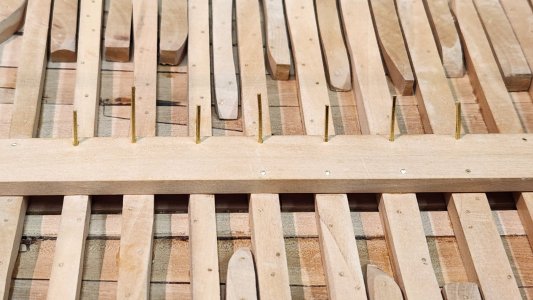
To create a sturdy construction I opted for 2 bolts conform E81 and of these two bolt 1 goes through the ligger into the keel. PS and SB bolt changes every second ligger to go into the keel.
See the nail arrangement on one side below. With long and short bolts.
After fitting the center zaathout.
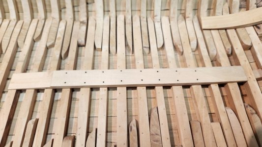
The forward part is fitted on top. The edges of the scarphs are nailed additionally to the bolts.
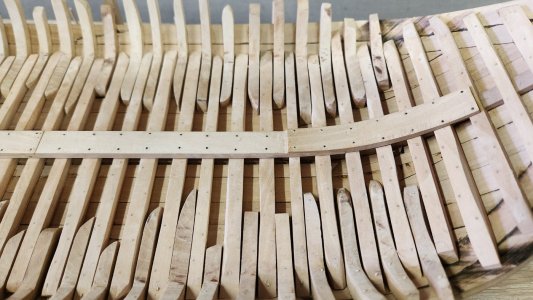
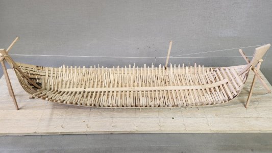
The whole zaathout is fitted, the backbone of the ship.
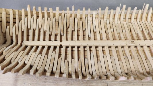
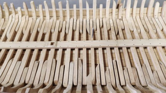
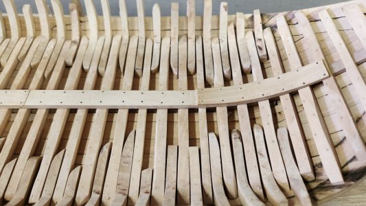
The mast step is nailed with it mast angle trim adjustment on the rear.
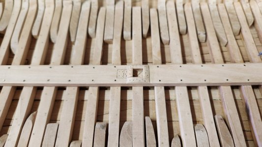
Next time we start the scheerstrook.
The size of the keelsom I have taken from the E81 Samuel wreck, which is with 95 Amsterdam foot the same lenght as my fluyt ship.
The keelsom width is 1 3/4 ft and a thickness of 2/3 ft.
It is composed of three parts, the aft part which is largest and contains two holes which are to my opinion for the pumps and the main mast foot. It connects via a scarph joint to the middle part and the curved bow piece.
See below the archeological drawing of these.


After preparing proper size strips the scarph joints are milled.

Until a proper fit is created.


In the long aft piece a mast step is created, it is situated in the center of the ship half way between bow and stern.
I have used again the E81 as an example.


And the original on Samuel.


At the bottom I have created a drain to avoid rot to the mast and keelsom. I have taken this from another wreck, the K47-II which was a freighter between 30-35 mtr from early 1700. It's zaathout is very comparable in size. See below the maststep picture from the archeological report of this wreck which is in a farm field in the Noord Oost polder., yes here in the Netherlands there are quite some shipwrecks in fields which were previously sea bottom

A next study was on the fastening of the construction.
I expected before the zaathout (keelsom) was fitted the liggers (floors) would be fixed to the keel. I had misinterpretated the paper "double dutch solutions in flush planked shipbuilding" of Thijs Maarleveld about the SO 1 wreck where he states

The liggers were only nailed on the edges to the planking for temporary fitting. Then they were treenailed to the planks, so still no fixing to the keel.
Only after fitting the zaathout bolts were driven into the construction.
See below again a picture of E81 here the zaathout, ligger and keel are shown with two bolts attaching the zaathout to the ligger. There seems to be no connection between ligger and keel which looks odd to me as this really weakens the construction.

Maarleveld writes in his SO 1 paper

This means minimum 1 bolt in each ligger from the zaathout. Every second ligger the bolt goes through the ligger into the keel.
On E81 there are two bolts in every ligger, see the drawing at the top and the picture below.

To create a sturdy construction I opted for 2 bolts conform E81 and of these two bolt 1 goes through the ligger into the keel. PS and SB bolt changes every second ligger to go into the keel.
See the nail arrangement on one side below. With long and short bolts.

After fitting the center zaathout.

The forward part is fitted on top. The edges of the scarphs are nailed additionally to the bolts.

The whole zaathout is fitted, the backbone of the ship.


The mast step is nailed with it mast angle trim adjustment on the rear.

Next time we start the scheerstrook.
Last edited:
Great work and research!After a great meeting in Amsterdam it was back into the workshop and work on the keelsom.
The size of the keelsom I have taken from the E81 Samuel wreck, which is with 95 Amsterdam foot the same lenght as my fluyt ship.
The keelsom width is 1 3/4 ft and a thickness of 2/3 ft.
It is composed of three parts, the aft part which is largest and contains two holes which are to my opinion for the pumps and the main mast foot. It connects via a scarph joint to the middle part and the curved bow piece.
See below the archeological drawing of these.
View attachment 474212
View attachment 474213
After preparing proper size strips the scarph joints are milled.
View attachment 474214
Until a proper fit is created.
View attachment 474216
View attachment 474217
In the long aft piece a mast step is created, it is situated in the center of the ship half way between bow and stern.
I have used again the E81 as an example.
View attachment 474218
View attachment 474223
View attachment 474224
View attachment 474219
And the original on Samuel.
View attachment 474220
View attachment 474222
At the bottom I have created a drain to avoid rot to the mast and keelsom. I have taken this from another wreck, the K47-II which was a freighter between 30-35 mtr from early 1700. It's zaathout is very comparable in size. See below the maststep picture from the archeological report of this wreck which is in a farm field in the Noord Oost polder., yes here in the Netherlands there are quite some shipwrecks in fields which were previously sea bottom
View attachment 474221
A next study was on the fastening of the construction.
I expected before the zaathout (keelsom) was fitted the liggers (floors) would be fixed to the keel. I had misinterpretated the paper "double dutch solutions in flush planked shipbuilding" of Thijs Maarleveld about the SO 1 wreck where he states
View attachment 474228
The liggers were only nailed on the edges to the planking for temporary fitting. Then they were treenailed to the planks, so still no fixing to the keel.
Only after fitting the zaathout bolts were driven into the construction.
See below again a picture of E81 here the zaathout, ligger and keel are shown with two bolts attaching the zaathout to the ligger. There seems to be no connection between ligger and keel which looks odd to me as this really weakens the construction.
View attachment 474231
Maarleveld writes in his SO 1 paper
View attachment 474232
This means minimum 1 bolt in each ligger from the zaathout. Every second ligger the bolt goes through the ligger into the keel.
On E81 there are two bolts in every ligger, see the drawing at the top and the picture below.
View attachment 474233
To create a sturdy construction I opted for 2 bolts conform E81 and of these two bolt 1 goes through the ligger into the keel. PS and SB bolt changes every second ligger to go into the keel.
See the nail arrangement on one side below. With long and short bolts.
View attachment 474235
After fitting the center zaathout.
View attachment 474237
The forward part is fitted on top. The edges of the scarphs are nailed additionally to the bolts.
View attachment 474238
The whole zaathout is fitted, the backbone of the ship.
View attachment 474246
View attachment 474239
View attachment 474240
View attachment 474241
The mast step is nailed with it mast angle trim adjustment on the rear.
View attachment 474242
Next time we start the scheerstrook.
The next step is a big one as it largely determines the shape of the vessel. In Dutch it is called the scheerstrook, simply said it is the line of greatest breadth following the line between the lower wales, allthough some vessels seem to defiate from this.
For my model I will follow the greatest breadth wales principle.
This means my scheer strook will follow the space between the two lower wales and this will also be the line of greatest breadth.
In the picture below this is the blue line.
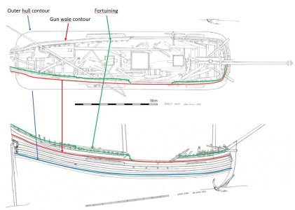
On the shipyards this blue line was most probably created by hanging a rope from the stern to the stem at the required heigth for the scheerstrook. In the middle this rope should pas the point of the greatest breadth which was at the holte(depth) of the ship. I have determined the start and end point by the run of the wales in the archeological drawing from Niklas Eriksson, but this could also be determined by the number of planks from the top of stem and stern.
The holte in the case of my ship is another discussion. In Dutch ships the holte, ×/- 1/10 of the length, is specified as the point of the lowest scupper, or the underside of the orlop deck beam to the top of the keel. My ship is actually a single deck fluyt with a koebrug deck. The koebrug deck is a simple constructed deck with ample height of around 5 feet height for storing cargo that needed to kept dry. This means my ship has no orlop and the lowest scupper is from the main deck. Van Yk actually mentions a different holte ratio for a single deck ship in his examples showing that this could be different for single deck ships.
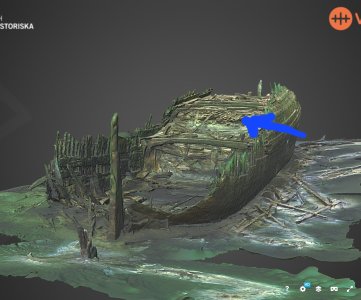
See below the planks stored on the koebrug deck of the Anna Maria wreck.
But next to the theory I do have a scan of the hull at the main mast and this shows the greatest breadth of the hull at the height of the koebrug dek.
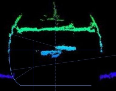
The two blue spots in the middle are the reflextion of the koebrug deck through the big deck hatch. This also seems to be the point of greatest breadth and the spot around the lower wales. Therefore I selected this as the point for my scheerstrook.
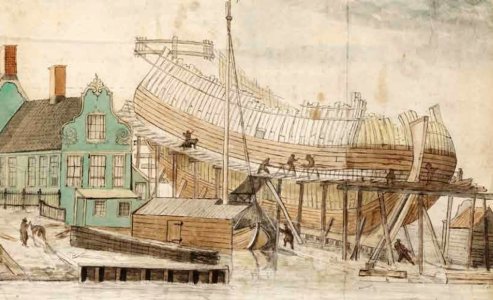
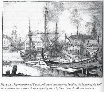
Now determining the run of the scheerstrook. As mentioned this was most probably done by hanging a rope between stem and stern. An example you see on this old contemporary prints for the higher situated wales.
I have done the same on my model. Instead of rope I used fine chain, this as rope doesn't work at scale because gravity and friction in the rope don't scale down.
A horizontal beam at the stern and stem are used to attach the rope.
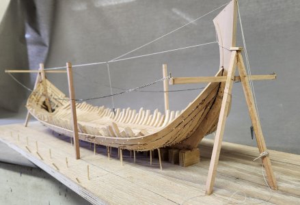
At the center frame at 1/3 of the ships length on both sides a vertical pole is set at the maximum breadth incl wales of the ship. On this pole the heigth of maximum breadth (holte) is marked.
Now a rope is hanged from the beams along the point of maximum breadth, this will be the flow of the wales and the sheer of the hull, suprizingly you see similarity between the word sheer in English and scheerstrook in Dutch.
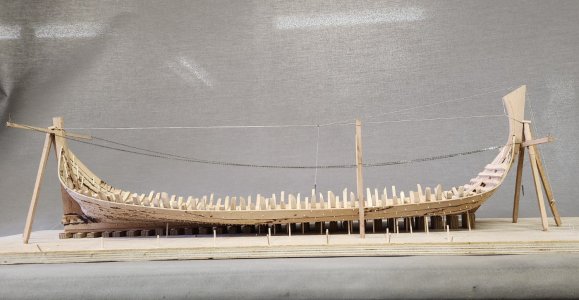
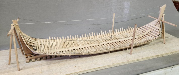
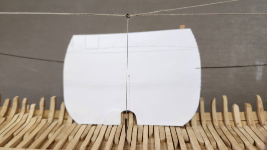
The line created is not an arc but a catenary, which is a line created by the gravity forcing on the rope due to its own weight. In my Fusion 360 this is rather complicated to draw but the simple chain in my dock yard is doing the tric.
Next time creating the scheerstrook and set up the correct shape along the hull.
For my model I will follow the greatest breadth wales principle.
This means my scheer strook will follow the space between the two lower wales and this will also be the line of greatest breadth.
In the picture below this is the blue line.

On the shipyards this blue line was most probably created by hanging a rope from the stern to the stem at the required heigth for the scheerstrook. In the middle this rope should pas the point of the greatest breadth which was at the holte(depth) of the ship. I have determined the start and end point by the run of the wales in the archeological drawing from Niklas Eriksson, but this could also be determined by the number of planks from the top of stem and stern.
The holte in the case of my ship is another discussion. In Dutch ships the holte, ×/- 1/10 of the length, is specified as the point of the lowest scupper, or the underside of the orlop deck beam to the top of the keel. My ship is actually a single deck fluyt with a koebrug deck. The koebrug deck is a simple constructed deck with ample height of around 5 feet height for storing cargo that needed to kept dry. This means my ship has no orlop and the lowest scupper is from the main deck. Van Yk actually mentions a different holte ratio for a single deck ship in his examples showing that this could be different for single deck ships.
See below the planks stored on the koebrug deck of the Anna Maria wreck.

But next to the theory I do have a scan of the hull at the main mast and this shows the greatest breadth of the hull at the height of the koebrug dek.

The two blue spots in the middle are the reflextion of the koebrug deck through the big deck hatch. This also seems to be the point of greatest breadth and the spot around the lower wales. Therefore I selected this as the point for my scheerstrook.
Now determining the run of the scheerstrook. As mentioned this was most probably done by hanging a rope between stem and stern. An example you see on this old contemporary prints for the higher situated wales.


I have done the same on my model. Instead of rope I used fine chain, this as rope doesn't work at scale because gravity and friction in the rope don't scale down.
A horizontal beam at the stern and stem are used to attach the rope.

At the center frame at 1/3 of the ships length on both sides a vertical pole is set at the maximum breadth incl wales of the ship. On this pole the heigth of maximum breadth (holte) is marked.
Now a rope is hanged from the beams along the point of maximum breadth, this will be the flow of the wales and the sheer of the hull, suprizingly you see similarity between the word sheer in English and scheerstrook in Dutch.


The line created is not an arc but a catenary, which is a line created by the gravity forcing on the rope due to its own weight. In my Fusion 360 this is rather complicated to draw but the simple chain in my dock yard is doing the tric.
Next time creating the scheerstrook and set up the correct shape along the hull.
Last edited:
- Joined
- Aug 8, 2019
- Messages
- 5,573
- Points
- 738

Good research, glad to see someone with the same explanations about the possible difference between the widest breath and the scheerstrook. Difficult on a fluyt to find the right spot for it. Because the absence of the orlop deck.
The only difficult point I have is, to determine the starting point of the scheerstrook on the stem. Witsen and Yk are not very clear about that. How did you solve that? On the stern it's clear, however a fluyt is a little different then a pinas.
The only difficult point I have is, to determine the starting point of the scheerstrook on the stem. Witsen and Yk are not very clear about that. How did you solve that? On the stern it's clear, however a fluyt is a little different then a pinas.
Hi Maarten,
Just a warning: Normally a ship had two lower wales. In case of fluits (and some more types) an extra wale was added....below the two mentioned. That means (if I were you) that your blue line of the scheerstrook (master ribband) should be placed between wale 2 and 3 reckoned from the keel up.
Just make your pick.
Last edited:
.
Hi Maarten,Indeed nice work, but I'm a bit on another subject. If you allow, this is probably a good place and time to point out that the term ‘koebrug’ changed meaning, say, around the third quarter of the 17th century.
Before that, it meant a deck above the main deck (overloop). This is particularly clear in the contract for the construction of the ship Fides 1615. There, it was decided that the ‘koebrug’ deck would be built in this ship instead of the lighter ‘bovenet’ deck, because some guns had to be placed on this level as well, that the structurally lighter ‘bovenet’ deck could not carry .
There are more clues of this kind in the sources, and if you need to, you can quickly check that van Yk also writes about this swapping of meanings, i.e. from the upper deck to the lower deck, in relation to the main deck – ‘overloop’ (in the contract for the construction of a large ship of 1629, pp. 157–166).
This swap of meanings is, incidentally, the cause of various misunderstandings today.
And good luck with your project.
Many thanks for the comments, remarks and questions.
@Ab Hoving, I wil certainly have a look at the slightly higher placed scheerstrook as I will be using the maximum breadth from the Eriksson drawing as a guideline.
@-Waldemar- many thanks for the additional info about the koebrug will dig into Van Yk again, luckel;y it won't impact the current construction. Regarding the shape of the stern I have found again a proportional radius for the curvature of the top view of the stern being a radius of 1/4 of the moulded breadth (Wijdte)
For the bow I still sorting this out, both will be part of a later post.
@Bela, copying the shape is actually rather simple and I will show it in my next post, regarding the the shape of stern and bow it is more complicated and i am still working on this.
@Steef66 this can be done by calculating the number and size of planks from the top of the gun wale down to in this case the space between the second and 3rd wale, which is 6 planks with a size of +/- 10 Amsterdamse duimen. Actually I took the measurement from Niklas Erikssons drawing.
Next is creating the scheerstrook.
As seen above the rope/chain is used for this, but before doing this I have to put my keel in a comparable angle to a Dutch yard floor.
According Kramer in his book VOC retourschip the angle of the yard floor in Dutch yards was +/- a ratio of 1:20 with the bow towards the water.
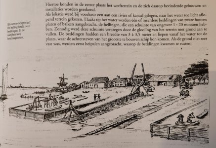
For my modelboard of 1 mtr this means 5 cm higher at the stern than at the front plus a compensation for the amount of stuurlast I had created in my yard blocks to build my model with an even waterline instead of an even keel.
This hight I have added to the rear of the building board.
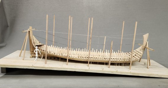
Effect of this is that the chains lowest point is moving slightly forward and suprisingly it moves to 1/3 of the length between perpendiculars where the centre frame is situated.
I have also raised poles around the ship to mark the maximum breadth at the outside of the wales, according archeological reports this maximum breadth is 7 mtr.
I have done the math and came up with the moulded breadth of 24 Amsterdam feet being 6794,4 mm.
I have been measuring the wales of the Samuel wreck, which are 4 Amsterdam inches (duim) being 283,1 / 11 x 4 = 102,945. If we add two wales to the 24 feet we get 24' 8" which is exactly 7000,29 mm. The scan they did on the ship reported 7 mtr, I would say this is pretty close to that.
With this fluyt being completele straight along the major part of the maximum breadth the poles are simply placed in a straight line.
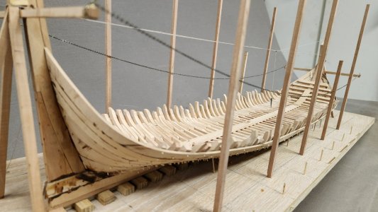
Now the poles are placed along the hull I can mark the places of the chain on them marking the run of the wale.
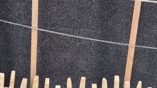
@Bela
To determine the shape of the wale and copy it to the wood they could use a batten with a even markings on it and keep it along the two markings on the poles above the chain or rope.
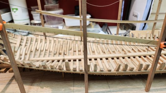
Now measure the space between the batten and the rope and write down the measurement at each marking.
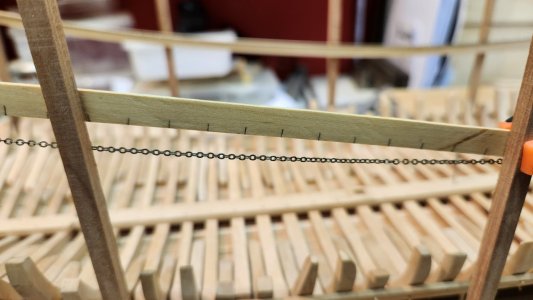
Remove the batten and put it on the wood to be used. Draw a straight line along the batten, copy the markings and set of the distances as written on the batten. Now connect all the end of the measurement and you have copied the run of the curved line.
I have made the scheerstrook of 4 pieces per side, a bended bow and stern piece and two straight centre pieces.
The scheerstrook was most probably a have piece of oak timber to carry the force of the oplangen which are placed between the zitters from the liggers to the scheerstrook and create a force towards the scheerstrook because of their angle of placement.
I have determined to create my scheerstrook at the same size as a wale being 4 duim thick and 10 duim wide.
After taking the measurements and sawing the scheerstrook on one side I scratch the width parralel of it with a caliper.
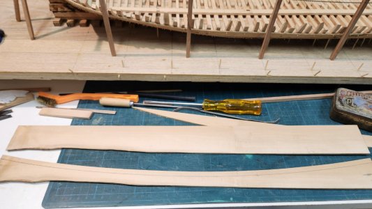
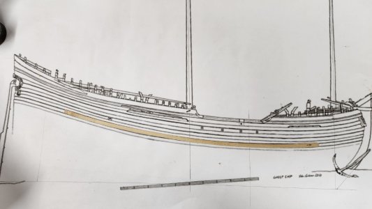
Comparing the sawn catenary scheerstrook with the Eriksson drawing.
Below I have installed the two straight parts on both sides.
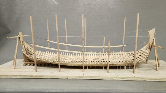
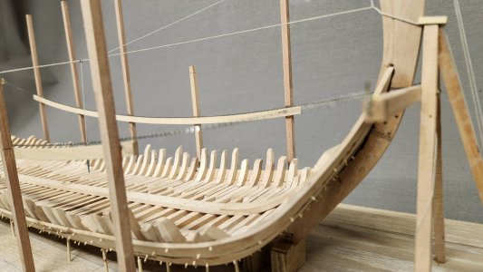
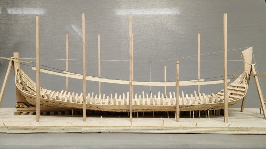
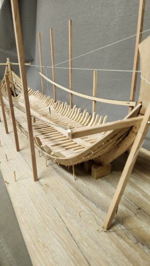
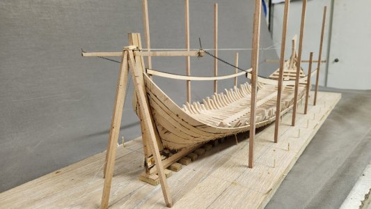
Via the construction methode with the poles it should have been rather easy to lift these heavy pieces of timber in place. To avoid that the poles would tilt due to the force of the placed oplangen the poles could have been connected to each other across the ship. The poles placed are on the high side and I will shorten them before continueing.
Next time the shape of the scheerstrook in bow and stern.
As seen above the rope/chain is used for this, but before doing this I have to put my keel in a comparable angle to a Dutch yard floor.
According Kramer in his book VOC retourschip the angle of the yard floor in Dutch yards was +/- a ratio of 1:20 with the bow towards the water.

For my modelboard of 1 mtr this means 5 cm higher at the stern than at the front plus a compensation for the amount of stuurlast I had created in my yard blocks to build my model with an even waterline instead of an even keel.
This hight I have added to the rear of the building board.

Effect of this is that the chains lowest point is moving slightly forward and suprisingly it moves to 1/3 of the length between perpendiculars where the centre frame is situated.
I have also raised poles around the ship to mark the maximum breadth at the outside of the wales, according archeological reports this maximum breadth is 7 mtr.
I have done the math and came up with the moulded breadth of 24 Amsterdam feet being 6794,4 mm.
I have been measuring the wales of the Samuel wreck, which are 4 Amsterdam inches (duim) being 283,1 / 11 x 4 = 102,945. If we add two wales to the 24 feet we get 24' 8" which is exactly 7000,29 mm. The scan they did on the ship reported 7 mtr, I would say this is pretty close to that.
With this fluyt being completele straight along the major part of the maximum breadth the poles are simply placed in a straight line.

Now the poles are placed along the hull I can mark the places of the chain on them marking the run of the wale.

@Bela
To determine the shape of the wale and copy it to the wood they could use a batten with a even markings on it and keep it along the two markings on the poles above the chain or rope.

Now measure the space between the batten and the rope and write down the measurement at each marking.

Remove the batten and put it on the wood to be used. Draw a straight line along the batten, copy the markings and set of the distances as written on the batten. Now connect all the end of the measurement and you have copied the run of the curved line.
I have made the scheerstrook of 4 pieces per side, a bended bow and stern piece and two straight centre pieces.
The scheerstrook was most probably a have piece of oak timber to carry the force of the oplangen which are placed between the zitters from the liggers to the scheerstrook and create a force towards the scheerstrook because of their angle of placement.
I have determined to create my scheerstrook at the same size as a wale being 4 duim thick and 10 duim wide.
After taking the measurements and sawing the scheerstrook on one side I scratch the width parralel of it with a caliper.

Comparing the sawn catenary scheerstrook with the Eriksson drawing.

Below I have installed the two straight parts on both sides.


Via the construction methode with the poles it should have been rather easy to lift these heavy pieces of timber in place. To avoid that the poles would tilt due to the force of the placed oplangen the poles could have been connected to each other across the ship. The poles placed are on the high side and I will shorten them before continueing.
Next time the shape of the scheerstrook in bow and stern.
Last edited:
I hope you added the thickness of both 'master ribbands' (scheerstroken) to the beam of the ship when you placed the poles to support them. otherwise you will end up with a ship that is just that size narrower than you aimed for.
Sorry, I now discovered that you did take them into account. I could have known....
Sorry, I now discovered that you did take them into account. I could have known....


