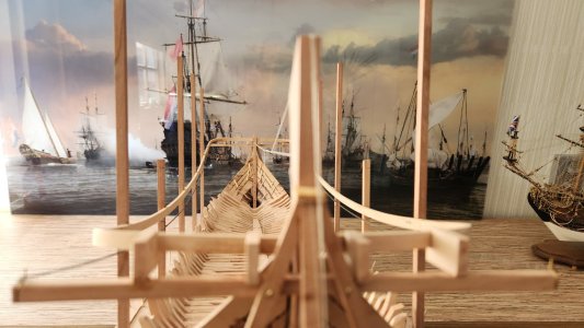
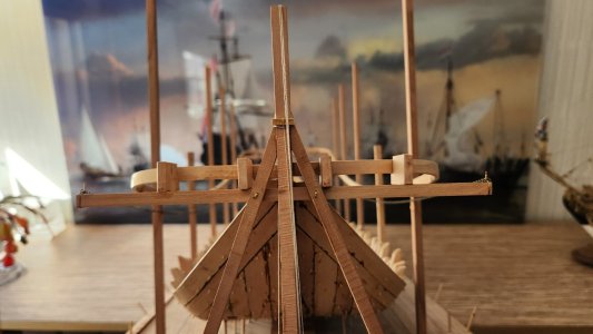
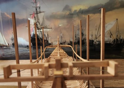
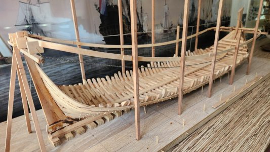
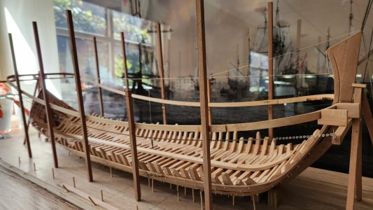
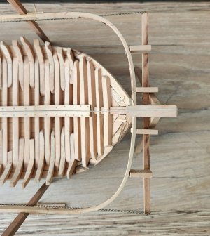
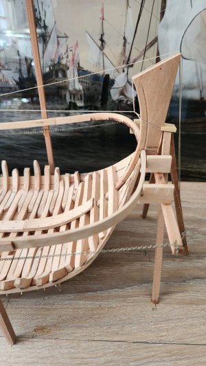
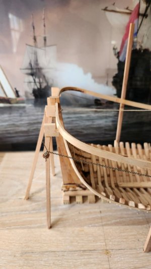
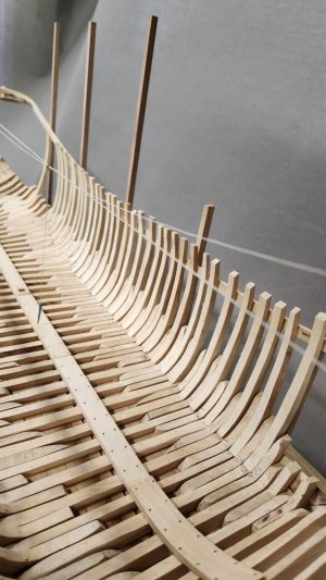
A Dutch Fluyt in shell first, reconstructing the "Ghost ship" scale 1:36

Maarten, I see that you applied the center sections of the master ribbands without the whole thing on the slope. You left out the height level. That's not how your master ribbands come out correctly, is it?

About the rising of the orlop deck there is something in Kamer's essay ("N.H. Kamer - De voorsteven van 17-eeuwse zeegaande schepen" written in "Tijdschrift voor zeegeschiedenis 20 (2001)") . He shows a table where he makes the comparison about the values given by Witsen, Yk and Grebber (whoever that may be), the difference of values is probably to be found about the time period the writers are talking about. Ships before 1650 showed a higher rising of the sheer. After that this was less. Yk is talking about ships from a later time frame. For every 10 feet of length between the stem, the rise was indicated in the table. From that data you can then determine the starting point of your master ribband on the bow.
Finally found an answer. I checked this in Winter's drawings of my Dutch 2-decker and it comes pretty close to the measurements of Witsen.

1728296008254.png

Those Dutch builders where smart in there building method. With only a certer with measurements of certain points of a ship they where capable to build those big ships with just pieces of ropes and gravity.
 
Next is creating the scheerstrook.
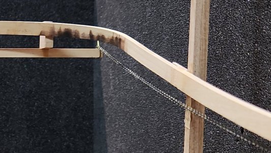
As seen above the rope/chain is used for this, but before doing this I have to put my keel in a comparable angle to a Dutch yard floor.
According Kramer in his book VOC retourschip the angle of the yard floor in Dutch yards was +/- a ratio of 1:20 with the bow towards the water.
View attachment 475152

For my modelboard of 1 mtr this means 5 cm higher at the stern than at the front plus a compensation for the amount of stuurlast I had created in my yard blocks to build my model with an even waterline instead of an even keel.
This hight I have added to the rear of the building board.
View attachment 475153

Effect of this is that the chains lowest point is moving slightly forward and suprisingly it moves to 1/3 of the length between perpendiculars where the centre frame is situated.

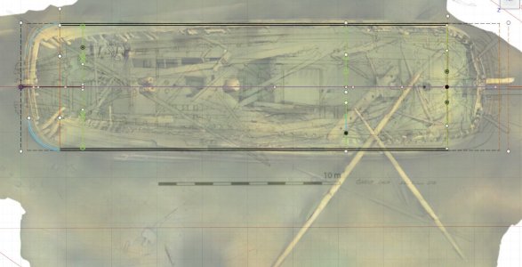
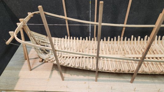
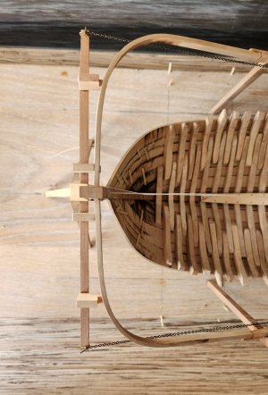
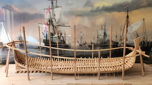
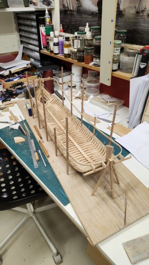
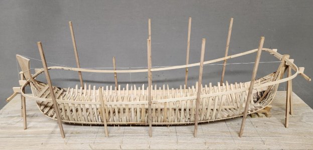
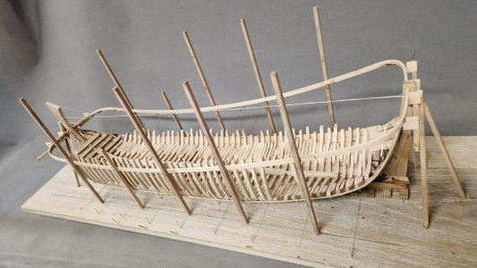
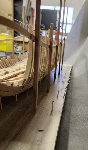
I have also raised poles around the ship to mark the maximum breadth at the outside of the wales, according archeological reports this maximum breadth is 7 mtr.
I have done the math and came up with the moulded breadth of 24 Amsterdam feet being 6794,4 mm.
I have been measuring the wales of the Samuel wreck, which are 4 Amsterdam inches (duim) being 283,1 / 11 x 4 = 102,945. If we add two wales to the 24 feet we get 24' 8" which is exactly 7000,29 mm. The scan they did on the ship reported 7 mtr, I would say this is pretty close to that.

With this fluyt being completele straight along the major part of the maximum breadth the poles are simply placed in a straight line.
View attachment 475154

Now the poles are placed along the hull I can mark the places of the chain on them marking the run of the wale.
View attachment 475273

@Bela
To determine the shape of the wale and copy it to the wood they could use a batten with a even markings on it and keep it along the two markings on the poles above the chain or rope.
View attachment 475275
Now measure the space between the batten and the rope and write down the measurement at each marking.
View attachment 475274
Remove the batten and put it on the wood to be used. Draw a straight line along the batten, copy the markings and set of the distances as written on the batten. Now connect all the end of the measurement and you have copied the run of the curved line.

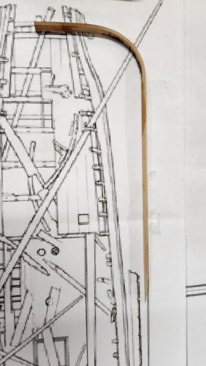
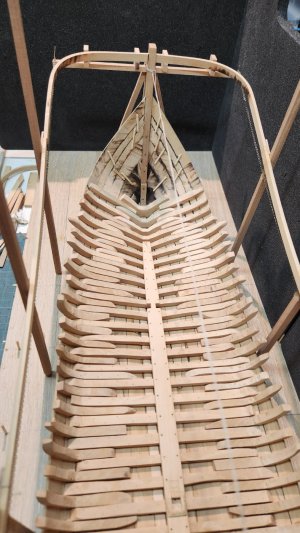
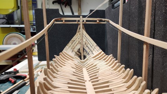
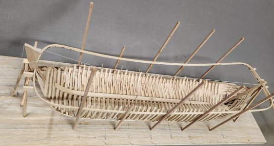
I have made the scheerstrook of 4 pieces per side, a bended bow and stern piece and two straight centre pieces.
The scheerstrook was most probably a have piece of oak timber to carry the force of the oplangen which are placed between the zitters from the liggers to the scheerstrook and create a force towards the scheerstrook because of their angle of placement.
I have determined to create my scheerstrook at the same size as a wale being 4 duim thick and 10 duim wide.
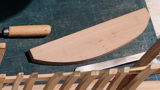
After taking the measurements and sawing the scheerstrook on one side I scratch the width parralel of it with a caliper.
View attachment 475740

Comparing the sawn catenary scheerstrook with the Eriksson drawing.
View attachment 475741

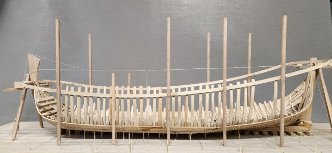
Below I have installed the two straight parts on both sides.
View attachment 475742View attachment 475744View attachment 475743
View attachment 475745
View attachment 475746
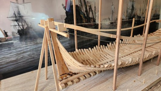
Via the construction methode with the poles it should have been rather easy to lift these heavy pieces of timber in place. To avoid that the poles would tilt due to the force of the placed oplangen the poles could have been connected to each other across the ship. The poles placed are on the high side and I will shorten them before continueing.
Next time the shape of the scheerstrook in bow and stern.
Very nice documenten and, above all, clarified with your photos, Maarten.
Regards, Peter
 
I hope you added the thickness of both 'master ribbands' (scheerstroken) to the beam of the ship when you placed the poles to support them. otherwise you will end up with a ship that is just that size narrower than you aimed for.
Sorry, I now discovered that you did take them into account. I could have known.... :)
Hi Ab, thx for thinking along. Yes I took them into account, that is also the reason for taking the scheerstrook as thick as the wales. The moulded breadth of the ship is 24 foot, the added wales or scheerstrook thickness is 4 duim on both sides, total width 24 foot 8 duim.

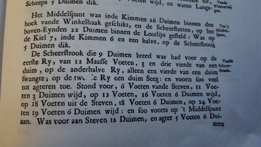
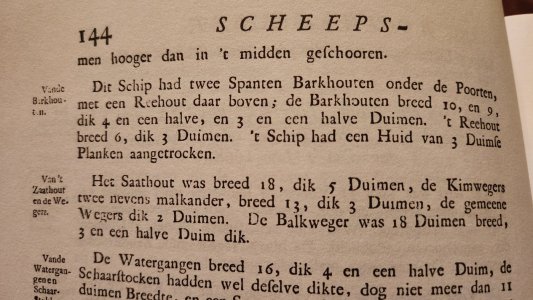
I have checked Van Yk also and he mentions a size for a scheerstrook of a 85 foot single deck ship being "9 duimen breed", mine is actually 10 duimen but my ship is 95 foot. So this seems to be within the ball park that Van Yk is mentioning.
20241007_193350.jpg

For the same ship Van Yk mentions that the barkhouten (wales) are respectively 10 and 9 duimen, which means that the scheerstrook is just as wide as the barkhouten. I did the same for my reconstruction taking the same width for the scheerstrook as for the wales.

See below the text from Van Yk.
20241007_214647.jpg
 
Maarten, I see that you applied the center sections of the master ribbands without the whole thing on the slope. You left out the height level. That's not how your master ribbands come out correctly, is it?

About the rising of the orlop deck there is something in Kamer's essay ("N.H. Kamer - De voorsteven van 17-eeuwse zeegaande schepen" written in "Tijdschrift voor zeegeschiedenis 20 (2001)") . He shows a table where he makes the comparison about the values given by Witsen, Yk and Grebber (whoever that may be), the difference of values is probably to be found about the time period the writers are talking about. Ships before 1650 showed a higher rising of the sheer. After that this was less. Yk is talking about ships from a later time frame. For every 10 feet of length between the stem, the rise was indicated in the table. From that data you can then determine the starting point of your master ribband on the bow.
Finally found an answer. I checked this in Winter's drawings of my Dutch 2-decker and it comes pretty close to the measurements of Witsen.

View attachment 475789

Those Dutch builders where smart in there building method. With only a certer with measurements of certain points of a ship they where capable to build those big ships with just pieces of ropes and gravity.
Quote "I see that you applied the center sections of the master ribbands without the whole thing on the slope. You left out the height level. That's not how your master ribbands come out correctly, is it?" Unquote

I took these from the 3D scan of the wreck as I did with the start and end points which I took from the archeological drawing.
I put the ship on the yard angle to get the run of the scheerstrook correctly, this has nothing to do with the 3 selected points.

Your second statement is correct if the rising of the deck is the same as the rising of the sheer. But during the 17th century the rise of the decks decreases, especially on war ships. The scheerstrook creates the sheer and does not follow the deck rise in all ships.
 
Now the scheerstrook in the sides is finished it is time to start on the bow and stern.
First the stern.
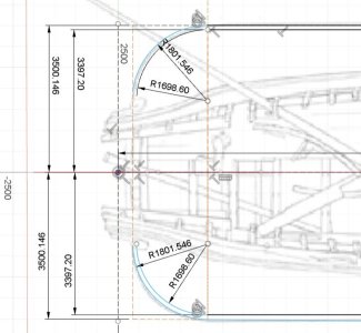
From the Eriksson drawings I have determined the radius of the curve. As the Eriksson drawing shows the outline I had to remove the 4 duim thick wale to determine the radius of the moulded breadth. I have done this in fushion 360.
Ghost ship stern design.jpg
The radius of the stern seems to be 1/4 of the moulded breadth, or 24/4 is 6 foot, being 1698,6 mm. When adding the 4 duim for the wale thicknes it clearly follows the shape of the archeological drawing.

Additionaly I checked it with the Tallinn fluyt wreck and this is very closely comparable.
Screenshot_20241007_230047_Gallery.jpg
Ghost ship vs Tallinn wreck.jpg

Now I have set the radius at 6 foot I can start bending the scheerstrook.
20241004_155801.jpg

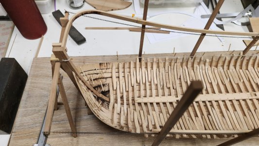
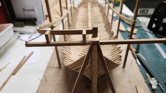
Tailoring it to fit its final spot. I have added to supports on the cross beam to carry the weigth of this part of the scheerstrook.
20241004_190402.jpg
20241004_190408.jpg

For the sb side the same process and copy a mirror of the ps side.
Both are now dry fitted.
20241007_203414.jpg
20241007_203426.jpg
20241007_203514.jpg

The contour of the fluyts beautifull stern is starting to appear.
Next time the bow.
 
OK, you have bent the Scheerstrook with a radius of 1/4 x width around the vertical axis, i.e. in the horizontal plane. But this connecting piece to the stem should also follow the curvature of the chain. So also in the vertical plane. How did you, and especially the old builders, determine this curvature?
 
OK, you have bent the Scheerstrook with a radius of 1/4 x width around the vertical axis, i.e. in the horizontal plane. But this connecting piece to the stem should also follow the curvature of the chain. So also in the vertical plane. How did you, and especially the old builders, determine this curvature?
Hi @Bela
This curvature is very minor as it is at the start of the catenary line.
Again uou can measure it with a batten like shown before.
I bended it on the heat plate and checked the run of it by eye.
20241007_203514.jpg
 
Next is the bow section, whereas the curve in the stern was a plain radius of 1/4 x width the bow is different.

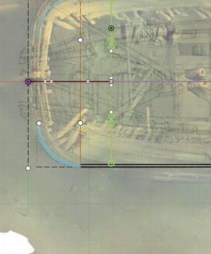
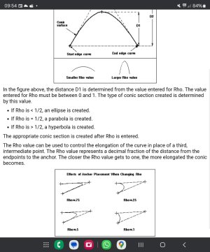
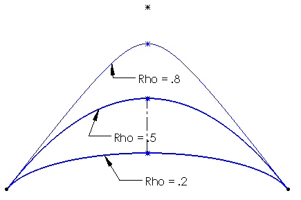
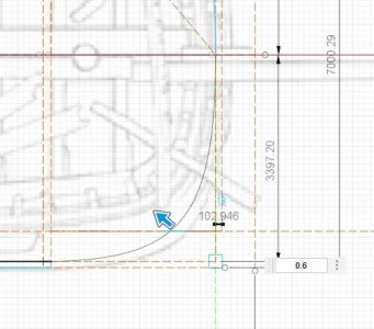
In Fusion 360 I have analyzed the radius of the scheerstrook at the bow as a hyperbola with a rho value of 0,6.
The rho value changes the curvature of the hyperbola shown below.
Screenshot_20241012_095409_Chrome.jpg
0001.png

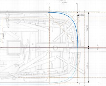
In fusion it is very simple to create this curve on top of the archeological drawing.
Ghost ship bow section curvature reconstruction.jpg
And create the correct curvature for the bow.

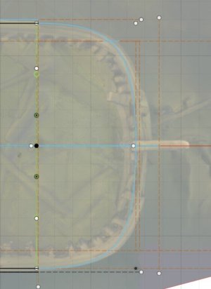
This same hyperbola shape can also be seen in the Tallinn wreck.
Ghost ship bow section curvature vs Tallinn wreck.jpg

But the interesting thing is how did the shipwright do this.
in principle we have a rectangular space in the bow where the curvature is drawn. In the ghostship this rectangle is 10 Amsterdam foot (2831 mm) from the bow and 12 foot wide (1/2 x moulded breadth = 3397.2 mm). This 10 foot is also the spot where the keel changes to the stem, in Dutch the knoop. This is also where Van Yk places his fwd frame, which I also used in determininng my hull shape. All these things comming together can't be coincidence and must be part of the design.

If I now draw a diagonal from the side to the bow followed by a squared line on the diagonal to the outside corner.
Next I draw a line from the moulded breadth at the gun wale forward. The moulded breadth at the gun wale being at 10 Amsterdam feet from the center.

We now see that the crossing of this line with the squared line is exactly at the hyperbola forming the bow section. This could have been used as marker point to draw the hyperbola for the bow shape.
Ghost ship bow section curvature reconstruction 2.jpg

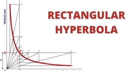
I am still working on a simple drawing methode of sketching this hyperbola on the yard as I don't expect complex calculus was used to do this. A default rectangular hyperbola drawing doesn't work as the curvature is incorrect.
rectangular hyperbola.jpg
I will come back on that later.

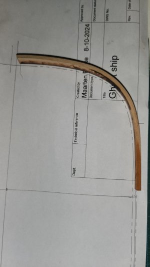
For the practicality of building the shape is now determined and I can start forming my fwd scheerstrook section.
After bending it follows my moulded breadth shape as drawn in fusion 360.
20241014_195251.jpg

Followed by fitting it in place.
20241015_131843.jpg

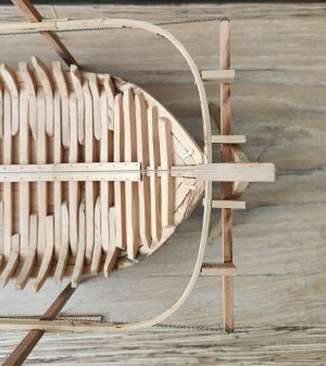
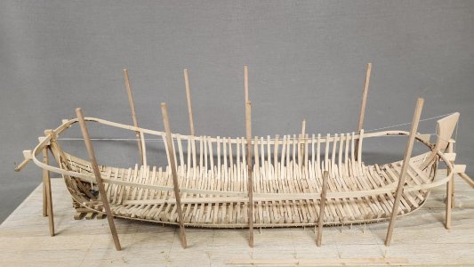
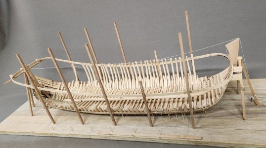
Now the complete scheerstrook is fitted and I can start by adding the oplangen (second futtocks). The shape of the hull is now really evolving
20241015_132140.jpg20241015_132125.jpg20241015_132053.jpg20241015_131923.jpg20241015_131857.jpg20241015_131843.jpg20241015_131837.jpg20241015_131814.jpg20241015_131826.jpg20241015_131758.jpg20241015_131746.jpg20241014_223544.jpg
 
Mathematics in a 16th century ships. These master on the shipyard where very educated. I discovered a time a go that mathematics also where used for juvenating yards and mast.
Thx for your comments gents.

There was most probably no math needed to draw these. I am still looking how this can be done by Geometry and will come back on that.

This means the people on the yard didn't need to know math to create these mathematical shapes.
 
Next is the bow section, whereas the curve in the stern was a plain radius of 1/4 x width the bow is different.

In Fusion 360 I have analyzed the radius of the scheerstrook at the bow as a hyperbola with a rho value of 0,6.
The rho value changes the curvature of the hyperbola shown below.
View attachment 477811
View attachment 477810

In fusion it is very simple to create this curve on top of the archeological drawing.
View attachment 477807
And create the correct curvature for the bow.

This same hyperbola shape can also be seen in the Tallinn wreck.
View attachment 477812

But the interesting thing is how did the shipwright do this.
in principle we have a rectangular space in the bow where the curvature is drawn. In the ghostship this rectangle is 10 Amsterdam foot (2831 mm) from the bow and 12 foot wide (1/2 x moulded breadth = 3397.2 mm). This 10 foot is also the spot where the keel changes to the stem, in Dutch the knoop. This is also where Van Yk places his fwd frame, which I also used in determininng my hull shape. All these things comming together can't be coincidence and must be part of the design.

If I now draw a diagonal from the side to the bow followed by a squared line on the diagonal to the outside corner.
Next I draw a line from the moulded breadth at the gun wale forward. The moulded breadth at the gun wale being at 10 Amsterdam feet from the center.

We now see that the crossing of this line with the squared line is exactly at the hyperbola forming the bow section. This could have been used as marker point to draw the hyperbola for the bow shape.
View attachment 477806

I am still working on a simple drawing methode of sketching this hyperbola on the yard as I don't expect complex calculus was used to do this. A default rectangular hyperbola drawing doesn't work as the curvature is incorrect.
View attachment 477814
I will come back on that later.

For the practicality of building the shape is now determined and I can start forming my fwd scheerstrook section.
After bending it follows my moulded breadth shape as drawn in fusion 360.
View attachment 477822

Followed by fitting it in place.
View attachment 477809

Now the complete scheerstrook is fitted and I can start by adding the oplangen (second futtocks). The shape of the hull is now really evolving
View attachment 477827View attachment 477828View attachment 477829View attachment 477830View attachment 477831View attachment 477832View attachment 477833View attachment 477834View attachment 477835View attachment 477836View attachment 477837View attachment 477838
Again a nice insight into how you work, Maarten. With a nice view how the shape of the ship is growing.
Is this statement correct:
"Thanks to a modern 3D program we now understand how simple it used to be?"
Regards, Peter
 
Again a nice insight into how you work, Maarten. With a nice view how the shape of the ship is growing.
Is this statement correct:
"Thanks to a modern 3D program we now understand how simple it used to be?"
Regards, Peter
Hi Peter, thx.
Regarding your statement I think especially the archeological reporting with 3D photogrammetry and 3D scanning helps us as simple hobbyist to have easy acces to the data. Secondly due to modern technology wrecks are found and accesable that weren't accesable a decade ago. This means there is just more data to compare and analyse.

Ofcourse our 3D drawing programs give you a quicker resolution to analyse and compare these individual wrecks.
 
Thx for your comments gents.

There was most probably no math needed to draw these. I am still looking how this can be done by Geometry and will come back on that.

This means the people on the yard didn't need to know math to create these mathematical shapes.
Van Yk explains how it was done on mast
Yk.jpg

You can make a parabool on a similar way, different of course but well known in these days. They don't have to known math but they certainly know how to use it in their building methods.
 
Back
Top