Adventure galley

Dave Stevens (Lumberyard)

Sponsor: dlumberyard
Staff member
Sponsor
Joined
Dec 1, 2016
Messages
5,095
Points
728

here is a simple and short creating a hull

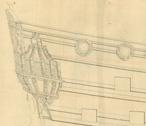
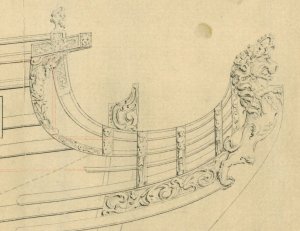
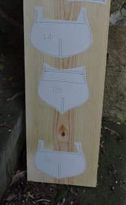
starting with a high resolution scan of the original
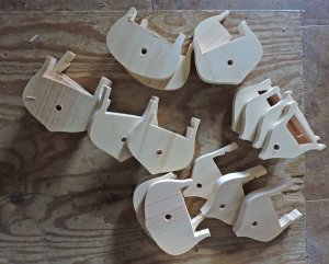
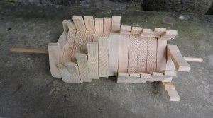
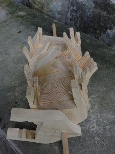
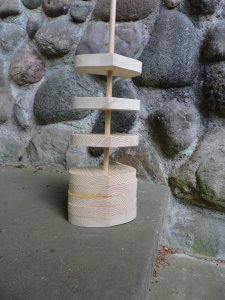
p1.JPGp2.JPGp3.JPGp4.JPG

I import the image into CAD and trace the station lines and the bodyplan the black lines are the original stations and the red lines were added.

pl1.JPG

here you can see the original bodyplan on the right and the final bodyplan with added bulkheads in red
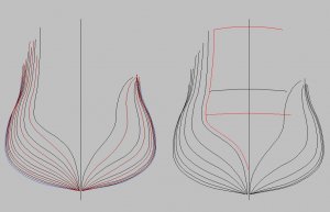
bp.JPG

one by one the bodyplan lines are lined up with the profile and the deck is added and the slot for the profile.
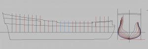
pl2.JPG

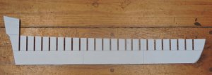
when all the bulkheads are drawn they are set up for a 8 1/2 x 11 printer. The profile is to long so it was printed in 3 parts and taped together.
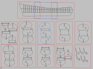
pl3.JPG
 
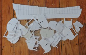
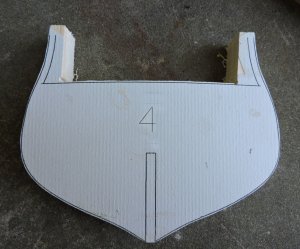
next step is a mockup to check the fit and make sure there are no bad bulkheads so foam board is used to cut out the parts

f1.jpgf2.jpg

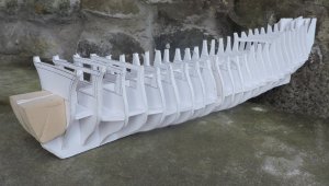
then a mockup hull is assembled the blocks at the bow were used only to square up the first bulkhead then bulkhead 2 was set square to one and so on.

f3.jpgf4.jpg

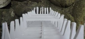
looking down the hull and under the poop deck

f5.jpg


now that the foam mockup looks good the next step is to build the hull out of wood. In this case a light weight easy to work wood will be used such as Cedar. the bulkhead and filler blocks will all be made of the same wood. I found by using plywood bulkheads and foam board filler blocks the filler blocks are way to soft and they do not sand equal to the plywood bulkheads so you end up with the bulkheads sticking out beyond the foam blocks. By using all the same material you will get a nice smooth hull ready for planking.

looking over the hull this will make a nice model it has the classic shape narrow, sleek and a beautiful tumble home to the cap rail. Looking from the side the curve of the sheer from the stern to the bow is just so nice.
 
Last edited:
cool but how do you get from the trace to the bulkheads. does the software do this?

I understand the body plan fine and doing all the bulkheads all by hand from the left/right for the hull shape.
but is there an automated process in the cad?

I have the means to cut them out accurately ( CNC / LASER) and the software to read pdf 1/1 images / vectors but the get from plan to those minus a hand draw of each no.


Not a cad fellow.
 
cool but how do you get from the trace to the bulkheads. does the software do this?

the drawing starts as a raster file which is imported into cad and the tracing creates a vector file that can be machine read for CNC or laser cutting


I understand the body plan fine and doing all the bulkheads all by hand from the left/right for the hull shape.
but is there an automated process in the cad?


the black bodylines are already on the original drawing it is just a matter of setting them up as bulkheads. now for all the bulkheads between the originals the red ones are done in CAD so cad is creating the curved shape of the red bulkheads by using a spline and plotting the shape from points i setup.

I have the means to cut them out accurately ( CNC / LASER) and the software to read pdf 1/1 images / vectors but the get from plan to those minus a hand draw of each no.

here is a topic I did on the Royal George it goes into detail on how this is done. The computer created frames or bulkheads are pretty accurate. I still do a foam board mockup just to check the work. sometimes the CAD program will draw an odd spline line. I can refine the process in CAD to get a very accurate shape if the hull is going to have all the framing. a bulkhead hull leaves room for a final shaping so they do not have to be within thousandths of and inch.

 
back to this project now it is time to build a hull

Cleveland Ohio was a major steel town and all the supporting machine shops and pattern shops for making patterns for casting.

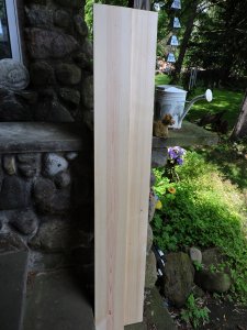
it might just be a local term but the wood for this hull is pattern pine and it was use to make the molds for castings. A pattern of the part to be cast was carved in wood then waxed. foundry sand was packed around the wood pattern and a mold created.

the reason this wood was used because for one reason you can get clean defect free boards

wh1.jpg

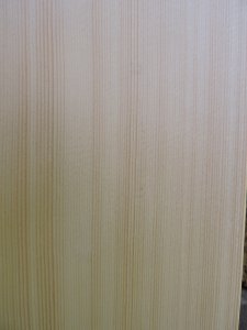
another reason is the grain is straight

wh2.jpg

and finally the grain is tight and fine so it is really nice to carve and holds a nice edge, it can be finished very smooth

wh3.jpg

So when you read forum members telling people you have to use such and such wood and only that wood they have no idea what they are talking about. The wood depends on what you plan on doing with it. In this application pattern pine is a perfect choice.

The hull will be built then sent off to a remarkable 3D artist and she will be creating the carvings. The hull will also be planked.

if you think this will be your standard plank on bulkhead hull well hang on this will be a totally different approach.
 
Dave,

do you have more information about the ship. The NMM drawing looks really interesting for me.

Take a look at this post I wrote in the Naval History Topic


and here:

 
The standard method for building a plank on bulkhead hull is to cut the bulkheads out of plywood, this is how kits are designed. The first thing after all the bulkheads are placed into slots in the profile piece filler blocks are used to fill the space between the bulkheads. Reason for the filler material is to shape a smooth hull with a full surface. Planking a bulkhead hull without filler material between the bulkheads creates flat areas in the planking and also the bulkheads are thin not giving enough surface area for a proper shape of the hull.

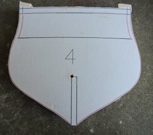
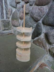
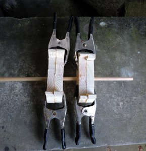
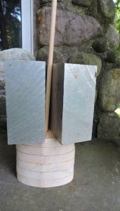
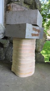
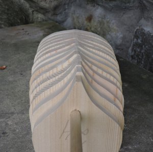
i am thinking outside the "standard" method for hull construction. If you need to fill the spaces between the bulkheads why not create bulkheads that are wide enough to fill the space. so what i did was measure the bulkheads from center to center which is 3/4 of an inch. Taking pine boards i surfaced them to exactly 3/4 and cut out the bulkheads.

wh4.jpgwh5.jpg

not using a center profile piece I needed another way to liune up the bulkheads to one another. The idea that poped into my head was to string the bulkheads on a dowel like a string of pearls. I needed an exact location on every bulkhead

wh6.jpg

i had the slot drawn on all the bulkheads so i punched a guild hole right in the upper corner of the slot, using a diamond tip i lined up the points to the lines

wh7.jpg
wh7.jpg

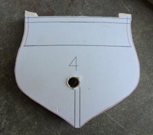
now it was just a matter of drilling a hole the size of the dowel in all the bulkheads

wh8.jpg

wh9.jpg
 
stringing the bulkheads on a round dowel did cause the bulkheads to spin 360 degrees. if I could of drilled a square hole that would have worked better. OR if I was using a laser I could have cut a square hole and milled out a square stick, but this did work out.

wh10.jpg

wh11.jpg
 
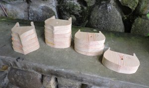
I ended up with sections of the hull

wh15.jpg

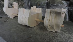
these sections were then strung on to the dowel. you may wonder why not just place each bulkhead on the work surface rather than usung the dowel? Well notice the bulkheads rise at the stern and bow off the surface so you need an X,Y location which is the dowel. i know this because i made this mistake once before.

wh16.jpg
 
what about those bulkheads spinning around the dowel?

that was no big deal I used the deck to line up each bulkhead

wh19.jpg

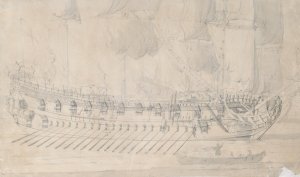
also sighting down the hull I made sure each side had the same space between one bulkhead to the other. you could measure the distance between the bulkheads on either side but just sighting it worked out fine. The hull is going to be sanded and given a final shape. If there is any misalinement a bit of wood filler will take care of it.
wh17.jpg

wh18.jpg
 
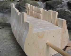
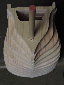
and that is how to create a core hull for planking in one operation without having to cut a center profile piece, bulkheads and add filler material.
when I get to the bow and stern I will post how I do that.
 
Hi Dave
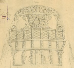
Can you tell me from which time the Plan is. 1676 I could see on the plan, but It looks like a drawing of the 18th. Century.
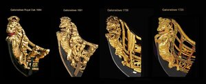
Especially the lion. Such a lion I know after 1702, because the lions before had no tailLöwen 17. 18. jht.jpg

regards
Willi (schifferlbauer)
 
Hi Jack
I know the date 1676 from the Plan, but are you sure that the plan is original from this time?

Willi (schifferlbauer)
 
I tried to find out, when the drawing of the Charles Galley, Dave is using, drawn - could not find something, but maybe Dave has closer info finding on the drawing.
As I understood, no drawings of the Adventure Galley of William Kidd is existing, so Dave is using a contemporary ship of the same type, size and period.
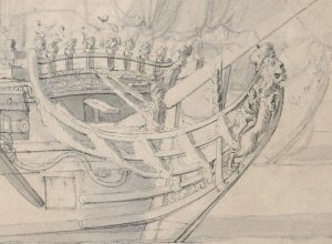
I know a painting from van de Velde the Elder (1611-1693), which was definitely painted in the questioned period.....and the Lion has no tail
2339.jpg

23391.jpg


Back
Top