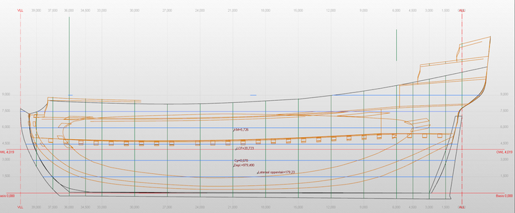
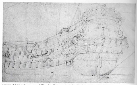
AKERBOOM 1681 after Ab Hoving nominally 1/66 but drawings in 1/64

Thanks Ab! '...apart from your head." Oh yes too true because than I would suffer from Morbus Robespierre ;)

Yes I did work with paper - on small card model ships 1/250 and for ships (Predreadnoughts) for naval tabletop in 1/750. I even used paper in 1/35 on plasticmodels and I am used to stiffen it by adding very cheap superglue by this the paper can get sanded at the very end. So I am a bit in this topic but a greenhorn in scratch building.

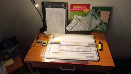
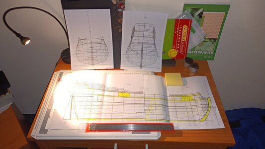
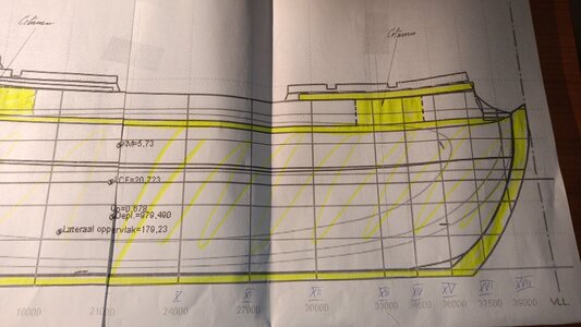
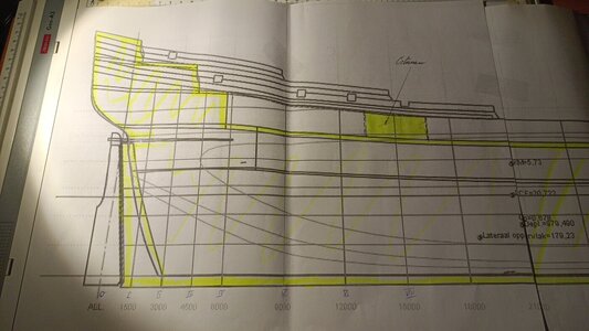
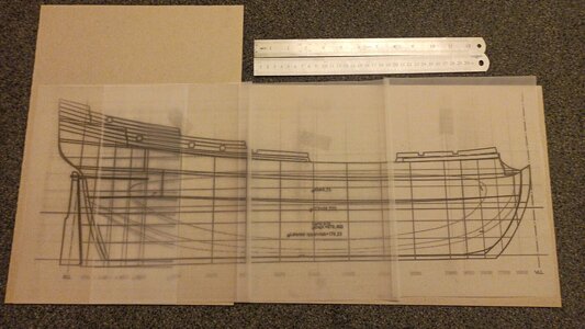
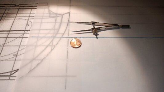
Today I just dealt with the hull side drawing copied on frostpaper to testfit:
View attachment 431685

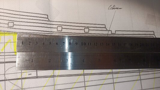
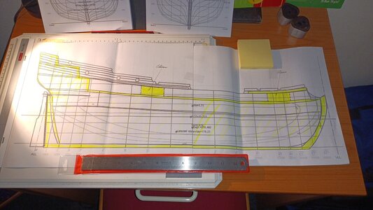
So I could look after the decks in both Views at the very same time:
View attachment 431683

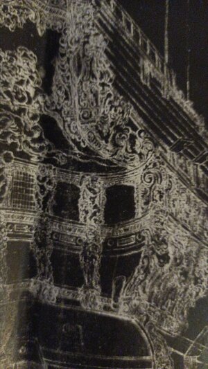
Pulling the frostpaper over the drawing shows clearly the graphical correctness of all lines to me.

View attachment 431684
This IS nothing against your drawings, dear Ab. But my expirience to the shrinking of paper in the xerox machine when I made copies. So this was all I could do today sadly.

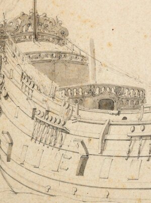
Recently I am looking in to the fore drawings of WvdV and do look for a solution to the Breakhead Bulkhead there are several solutions smaller ships with a pair of doors,
View attachment 431698

big ships with only a single door,
View attachment 431701
or medium sized ships with doors and gunports:
View attachment 431700

But I excluded this beauty as she looks too old (due to the lang gallion) and too English (die to the BrBu's decor and the round turret on the QG)...
...am I right?
View attachment 431699
This is Ab's solution two doors and outside two gunports...

View attachment 431706
...but why you did chose this solution - the knispeldrawing shows nothing like this:
View attachment 431705

So my question stayed afloat: Hmmm, what of them is right for the Amsterdam's yard of 1660-1670 for a 60-gun ship?

Any suggestions?

View attachment 431702

View attachment 431703
Hi Chris. I am following your thread with great interest. Mainly because of the not often use of paper/card. A bit unconventional build is always nice.
At first I hope that your hand will recovered quickly.
About the shrinking of the paper in the Xerox, maybe you can give it a magnification factor (101%-102%)?
Regards, Peter
 
So my question stayed afloat: Hmmm, what of them is right for the Amsterdam's yard of 1660-1670 for a 60-gun ship?
If there is one thing you should have noticed by now, studying all these wonderful ship's portraits: there is only one golden rule, namely, that THERE IS NO GOLDEN RULE. In Dutch design of decoration and layout of ordnance many many things are possible. There are no laws that command or forbid shipbuilders to do so and so, except practical limitations. Of course there are indications, advices, rules of thumb, everything you can think of....but no laws. If you are looking for strict regulations to apply to your build, forget it. If you think my drawings are the only possible way to build a ship like the one you are after, I have to disappoint you. Almost everything is possible. So don't ask me for a guarantee that everything in the drawings is absolutely historically correct. What you see is the sum of decisions I made, based on the same sources you show here. I try to combine the knowledge we have of the way these ships were designed and constructed with the pictures that were made by contemporary artists. Thanks god for them and for the written sources like Witsen and Van IJk. There are so many 'blanc areas', where we simply don't know anything about. Every day I discover newly found ones.... All the rest is interpretation. Feel free to change whatever seems illogical to you. Your bet is as good as mine.
Good luck.
 
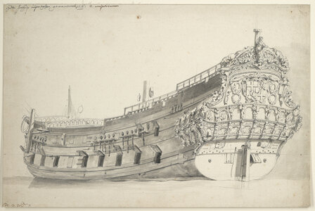
Oh, Ab, I think it is a pain and a pleasure to deal with Dutch shipbuilding - so I will look for the "Vreheijt" I do get and deal with the rest struggling with your knowledge and keep asking stupid questions. So if it isn't enforced by picture everything is possible - so I do have got the transom views of both sisters by WvdV and so I will try to work with this unknown freedom I am affraid of - hopefully not becoming a ugly kind of freeDOOM.

So in this nice topview plan:
top view.PNG

I did figured out the positions of the gunports and can transfere these into the side view:
Schermafbeelding 2024-02-25 om 14.23.44.png
As I never cut my gunports from scratch out of a hull:

And tomorrow then I will have time to deal with the hull, it's details and planking. Here:
fig 1.png
it looks like the gunports lower line weren't horizontal but parallel to the run of the deck?
Screenshot_2024-02-24-22-33-05-107-edit_com.android.chrome.jpg
So here it looks as the gunports lids were rectangular, but are they?

IMG_0119.jpeg
1.
So the lower edge of the gunports is a line parallel to the gun decks?
2.
But the gunport lids rectangular not a parallelogram.

Is this right?
 
Last edited:
Herman is right, that seems the most logical solution.
Still, this is a subject that led to furious debates on Dutch forums. Some say you have to follow the line of the wales, others argue that the line of the decks should be followed. On contemporary models I have seen both versions. Personally I think the line of the decks is the best option, because the gunports were cut after the deck was installed. Imagine looking at a gunport from the inside and noticing that one side of the sill is higher than the other... Odd.
The same goes for the lids. Recently an original gunport lid was found during an archaeological project in the Buishaven in Enkhuizen. Beautifully preserved with all the ironwork in place. And as square as can be.
Still, as I said, there is no iron rule, there are just possibilities (and in most cases the difference between a square and a parallellogram on model scale is too tiny to get upset over).
 
Last edited:
Thanks a lot Herman and Ab, that sounds reasonable and as the gunports do cut the wales,
py3859 (1).jpg

too, it is logical to follow the deck's line. In here VdV didn't show the "Cut Out" of the wale atop of the open lid - but I think the have to be added. In particular as they are "suddenly appearing" ;-) in an other drawing (luckily AKERBOOM) when the gun port is closed:
Akerboom.jpg

My hand is going to get better, so I will start these days with further progress on the drawings board.

One economical question:
As the seven provincinen weren't very large - where does all the oak wood do come from for the Admiralities' yards? One English two decker was eating a hole forest I do remember right?
 
Thanks a lot Herman and Ab, that sounds reasonable and as the gunports do cut the wales,
View attachment 432623

too, it is logical to follow the deck's line. In here VdV didn't show the "Cut Out" of the wale atop of the open lid - but I think the have to be added. In particular as they are "suddenly appearing" ;-) in an other drawing (luckily AKERBOOM) when the gun port is closed:
View attachment 432624

My hand is going to get better, so I will start these days with further progress on the drawings board.

One economical question:
As the seven provincinen weren't very large - where does all the oak wood do come from for the Admiralities' yards? One English two decker was eating a hole forest I do remember right?

I understand that for the larger ships the wood of 2000 or more trees was needed. Largely oaks of over 100 years old. So there certainly was a shortage of wood and not only in the Dutch provinces. But as the Dutch were experienced traders they had less problems importing wood than the surrounding seagoing nations. Origin mostly from Germany and the states around the Baltic, e.g. Denmark / Poland / Russia. Research proved that the oak from the Baltic states was of very high quality.
 
Last edited:
Thanks, Herman, to your interesting reply. An astonishing ammount of wood and by this certainly money - naval warfare never was a cheap kind of writing history, wasn't it?

Dear Ab thanks for the clarification on the case of the lids. That is really an interesting point to discuss.

Dear Peter, thanks a lot I do first steps foreward and am really unshure what cardboard can do - and still think about the unanswerable questions, lecks of skill and possible risks to ruin my AKERBOOM more than the chances ond offers (part of my illness I do guess).


Dear friends,

I came to the hospital a few days before and managed to reinstall my drawings board in my small room:
IMG_20240314_170625_396.jpg

As I am quite unteached in Dutch shipbuilding and do build my real first step into such a big card work
IMG_20240314_214131_270.jpgIMG_20240314_214101_693.jpg

I do like to stay cowardlike on the save side...

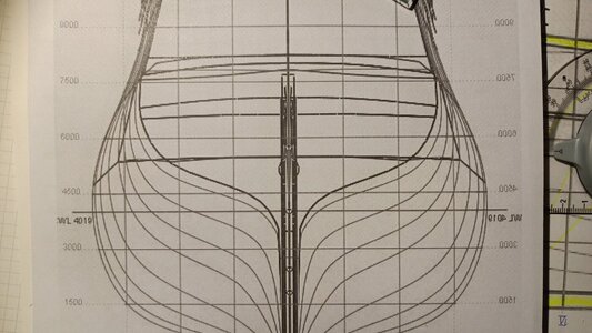
And I started the construction process by dealing with thoughts about the shape of the centerboard before the main frame:
IMG_20240314_190120_299.jpg

...and after:
IMG_20240314_190101_573.jpg
As the decks are quite long in the back and quarter my idea is to add there and there a hidden column (painted brown-grey) below as a stanchion. By this static structure I do hope avoiding any risk of a slaggy deck.
IMG_20240314_214413_063.jpg
Being 224mm/8-3/4" long it does really need some support even being bent.

IMG_20240314_214646_761.jpg

The backdeck in particular is a problem as there shouldn't be any supportive structures...

A)
...perchance a stove/galley making my day?

B)
Where these "big fat Dutch gals"* equiped with wooden stanchions between the decks (as the French)? Due to the plan to paint these stanchions bright to camouflage the static structure even more by these "eyecatchers" distrackting the viewer attention away...
...hopefully.

To add more stability to the hull I think of filling the accomodations behind the transom mainly. Secretly playing on the idea with a wrong captain's chamber behind the clear windows' front...
Polish_20240314_192424530.jpg
As the outside pairs of windows are blind (due to privacy)...
IMG_20240314_220735_647.jpg
...even in the much more detailled drawings by WvdV of her sister GIDEON weren't any further helpfull hints.

C)
I do think they are painted as fake-windows or what was applicated there? Or weren't there any panels or windows to give that smelly room a good amount of steady fresh air?
(I did by editing cut the article short - leaving more for the next step.)

Best wishes from the hospital,
Christian
___________

*
 
Last edited:
Hello Chris,
Good to hear you took your plans with you to hospital. Hope they will get better soon, along with you. :)
In my personal experience in hospital there is so much fuzz around your bed that you don't even get a chance to think of anything but answering to questions of nurses, consuming your pills, receiving even more people who want to examen certain aspects of your health, fellow bed-lyers who want your attention and so on and so further. But a man needs a dream, so you made a good choice with concentrating on a ship model.
Interesting to see that you expect your decks to sag. I never had that problem, and neither had the Dutch ships in those days. I remember the English being jealous because of the fact that we had enough good wood to make our deck beams from one piece. They always had to make them out of two pieces and yes, they had stanchions to support their decks, which we never had.
Make the best of it Chris, we want your report of the build of your Akerboom.
Best,
Ab
 
Thanks a lot Ab!
As this is a hospital for the mindly (mainly stroke) and psychologically (burnout/depression) handicaped there is less fuzz here and (due to shame) are less visitors entering the place at all - it is the loudest at the smokers' hut of the nurses.

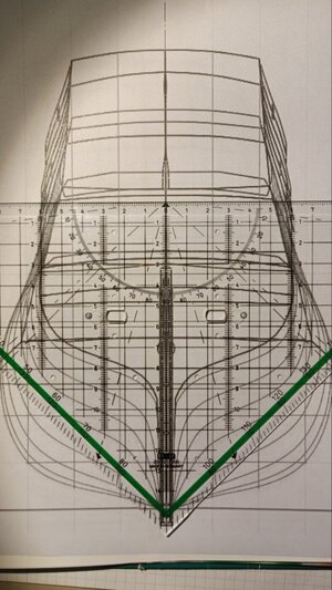
The test of the frames' plan showed a minimal discrepance between the starboard and portside on the transom's line - due to the helping lines of the geo. triangle it is hopefully easier to see the steeper rising on the starboard side:
Polish_20240315_132402645.jpg
I do think of leaving everything in this way as this is in it's self a test build.

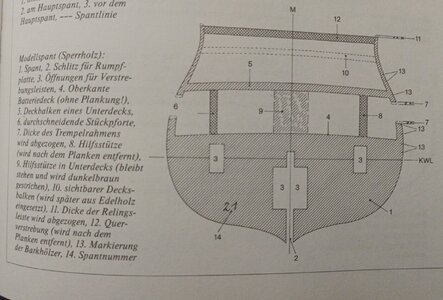
So I will start to draw out the bulkheads and do have to deal with the bulkheads "hitting" any gunport:

Polish_20240315_133326715.jpg
(zu Mondfeld, Historischer Schiffsmodellbau)

Polish_20240315_133404708.jpg
(zu Mondfeld aaO)

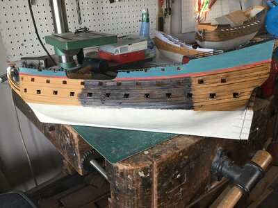
So before this I will have to locate the gunports over the weekend by this picture of As' AKERBOOM model:
IMG_0406.jpeg
So I can locate the run of the wales, too. After this the slots for the bulkheads are to be planed. Than I can start with the construction of the single bulkhead pice for pice.

That's the plan for now - have a great day and do net let yourself temptate by the warm weather - the center of our world's gravity lays in the workshop as humble it may be...


...only a well armed garden fleet makes your gold fish pont a pont worth to remember!
 
So many miracles in this world! A computer mirroring things and producing differences from one side to the other? I did not know that was possible.
Your stay there gives you remarkable powers!
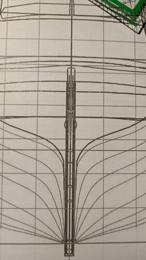
Sorry for telling you, Ab, but behold this for it is an error:
IMG_20240315_183226_635.jpg
Exactly in here where the deadwood is left:
IMG_20240315_183621_941.jpg

Or the weekend's doc will have to alter my medication again?

Edit:
Or it may depent on my ruptured retina in my leading left eye...
...this would be the worst case for hobby if a part of my eyesight would be deformed!
 
Last edited:
Don't worry Chris, if the difference (possibly caused by a printing issue) is so small that I can't see it, it certainly will not show up once you have turned the plans into a paper model.
 
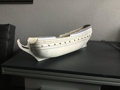
Hello Friends! Today the Center Board is Pplaning is got ready - six 2mm cardboards will become it.
So I do have the thickness of the keel to 1mm ready only by the CenterBoard! Than the two layers of 0,5mm plastic plate to clad the cardboard do give the missing millimeter to the keel. Pictures do come tomorrow evening to you.
Due to the shire size of the hull I do think about not only one deck layer but a second one in the CWL.

@Ab Hoving Three questions for you, Ab:
I.
What do you think about my plan - is there any error in your expirience?
II.
And is it a reasonable idea to use bent slots for the Verdeck to have this important and big item in the right way readyly curved in place?
III.
As the 39.000mms weren't a one piece keel - how the Dutch shipwrights did link their keel beams into eachother?

Thanks for your intrest.
 
Good morning Ladies and Gentleguys, it is 0430 and I am awake as everyday, so I thoughts to Made my contract sound sending the promised picture of the hull's Center Board arrangement at first:
IMG_20240320_044546_789.jpg
As allways the rulers in two languages (12" and 305mms) in the top right.

The hull as a hole (frostpaper mosaik) on the two cardboard sheeds (thickness 1/3 of need or 2mms or some7/8"). Ontop the next two cards are to be placed (left to right) long and upright and the thrid layer will copy this very arrangement to get a stiff and solid "backbone" - hopefully. Here inside the yellow lines (keeping the ruddder seperatly) going high up behind the transom:
IMG_20240314_214101_693.jpg

The rabbit's groove will then be cut in by a chisel - so my recent planing.

At the very end the keel is to be cladded by plastic card to imitate the wood (and it's structure) of this mighty "bar".

Progress is slow, as I do need hours for the simplest steps and I have to check everything twice due to deeply mistrusting my eyes and my hands' results.

That's all from the Card Yard.
 
Last edited:
Hello Chris,
Good to see that you make your time in hospital useful and productive.
For a ship with lower port holes closed this is a good set up. I'm not sure what you mean with 'bent slots' for the verdek. If you mean the supports you draw, it's ok, but not really necessary. But if you feel that is a good approach, please do so, you can always remove them if they don't work. This is what a joint in the keel looks like:
Schermafbeelding 2024-03-20 om 16.31.13.png

As to the idea to cut the rabbet in the keel with a chisel, I would not advise you to do it that way. You want to paste on some 0,5 mm plastic on both sides of the keel? That is enough to form your rabbet. Same for the stem and stern.

Hope this helps, good luck,
Ab
 
Thanks Ab,
I had thoughts about a curved slot to get the curved deck.

Thanks for the great advice with the rabbet - that sounds very much easier to work on.


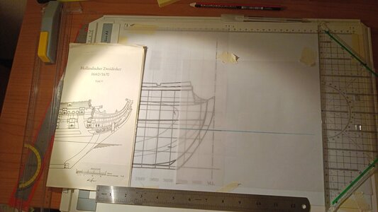
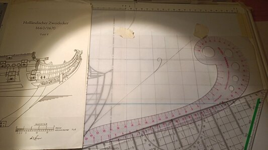
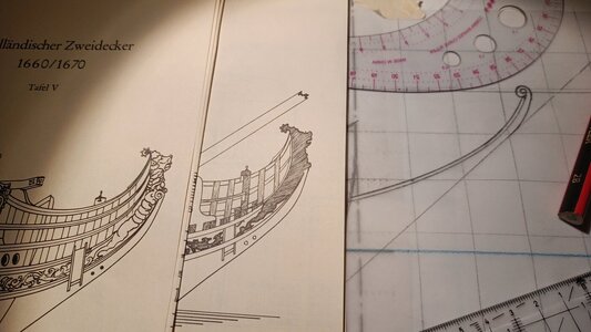
Today I did some first steps on the gallion and decided to follow Ab's tip to make good use of the Winter's drawings from "The Dutch Twindecker of 1660/70" (sideview of the plan set on the left) and so I started with the CWL on frostpaper:

Polish_20240320_205021155.jpg

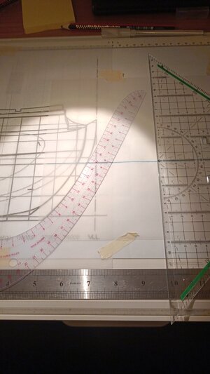
Here the copying of the stem's line by using a taylor's rulers set from China. Not the best quality at all but much cheaper than a Hamburgian curved ruler set for €300,- plus p&p...
IMG_20240320_200238_045.jpg
Here I am in the process of copying the 22×22mms grit from the AKERBOOM's drawing to get an orientation when xeroxing the hole sheet:
IMG_20240320_202455_777.jpg

Xecoring is the main reason not to draw on minimeterpaper at all. So here I added the 40° line of the gallion and the "tuber carvings" near the figurehead:
IMG_20240320_203813_680.jpg

Here the first item ready:
IMG_20240320_204415_955.jpg

Did I do untill now correctly?
 
Last edited:
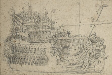
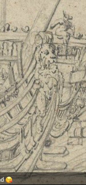
THE FIGUREHEAD QUESTION

So it is not allways a Lion, my wife teaching me this night on an undoubtly original and contemporary document by WvdV portraing very detailled an unknown French 70-gun ship:
70E6B84F-3B0B-4283-8BD8-8064C5991799.jpeg

...as sometimes it is a poodle:
IMG_20240321_090546_226.jpg
Or only aboard French ships?

*funfact off*
 
Last edited:
THE FIGUREHEAD QUESTION

So it is not allways a Lion, my wife teaching me this night on an undoubtly original and contemporary document by WvdV portraing very detailled an unknown French 70-gun ship:
View attachment 436409

...as sometimes it is a poodle:
View attachment 436407
Or only aboard French ships?

*funfact off*
Hello Friends of the old graphics, does have anyone of you an idea what ship this is that WvdV portraited? The figurehead allone is worth building it (later) at all.

Btw you could copy the vdV-drawing and place it behind the model...
edit: also for AKERBOOM and later

Polish_20240321_191831583.jpg


GIDEON, as there is only a place on the wall with a three (four with top for light) windowed case to place her in:
Polish_20240321_192157882.jpg

Polish_20240321_191831583.jpg
 
Back
Top