Alex R H.M.S. Enterprize Build Log

Do you sleep ? Do you have children laboring on your ship 24-7 _. You are moving FAST....___Congratulations..
AR
One of the benefits of a lousy spring so far in the Northeast, making hay while I can.
Once the weather breaks around here, it’s car season( big sportscar nut) and flyfishing for trout. You’ll catch up.
 
The keel structure is now in the building jig !
A few comments for the build group:
If you haven't built the jig-
1)keep the parts so that the layered number is towards the bow...Thyer external surfaces of parts B6 and A6 should be smooth, no parts should protrude.
2)in step # 3 -platform, parts A 12 and B 12 go at the top. The build drawings show part A 11 in at the top, bow side. The part number is wrong. The part is A 12. (B 12 plus A 12 are the parts that make up the top of the side bands.)
3) The bow keel structure fits well in the front, but there is a 9/64 " gap between the sternpost and the stern support on the jig. I don't think I missed a piece, but I'll check. If anybody knows (Victor) or is at this stage (Corsair) ? Help..
View attachment 513253View attachment 513254View attachment 513255
Full keel in jig. 9/64" gap between sternpost and jig stern support. (why?) Bow deadwood fits well
Thanks

Alex R
.
The problem is the slots in parts B13 and B14 in the construction jig. You taper down the aft end of the inner post and then glue on the stern post A13 which does not get tapered. I was going to ask Victor if the slots in B13 and B14 are wrong or if A13 should also be tapered. Without talking to Victor, I would probably opt for enlarging the slots. I would be afraid of changing the length because of all the slots for the frames both in the false keel and in the construction jig will all be thrown off possibly.
@Modelship Dockyard Victor, do you have any answers or suggestions?
 
Last edited:
Hi Alex, the two horizontal parts (B-13, B-14) on the back of the jig have the slot thinner than the keel. This was designed like this as there will be trimming of the stern post, so that it might get loose if we cut them wide. Players can use a file to sand down part of the slot, and to let the keel securely fix.

For the issue that there is a space at the bottom (or front), in theory they should be fine but we might have sanding a bit more during the building of the keel, I have also experienced this the gap was a bit smaller. Some modellers finished with no gap so it really depends. But it won't affect the making of your model, your way of putting a filler there will be fine.

It seems there is a issue however, that the sternpost should not be all tapered, it should be like what's shown on the image of Step 14 - D. What I suggest is to remove the sternpost carefully, and then cut a shape of the same size of the sternpost from sheet A, then install it back on, and do the downwards taper. If you find difficluties doing this, please let me know and I can send replacement.
Thank you again for your reply !
 
Worth a mention/ question, with your solution keeping the post somewhat away from the jig, will it, perhaps, throw the geometry off slightly when setting up the upper structure? This is what I scratched my head about and ultimately decided to insure the post was tight against jig.
All to be discovered down the road, but I offer up my thought process.
Very good question..
great ? minds think alike..

Essentially, the keel needs to be positioned in a stern to bow direction on the jig so that the frame positions on the keel correspond exactly, perpendicular, to the keel (for non-canted frames) in line with the slots for each numbered frame on top of the jig.

Here's what I am going to do: Find the location of a clearly identifiable midship frame on the keel, and looking straight down see how well it corresponds to the position of the frame on the jig for that frame-thankfully the location of the frame on the upper part of the jig is laser printed. I'll use a drafting T rule to do this (will show in a picture).
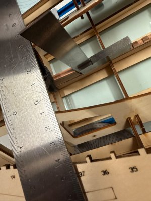
The picture shows that frame 37, the last midship frame, according to the plan, abuts the stern deadwood. The T ruler is positioned on the jig right on the slot for the posterior edge of frame 37. The 90 degree weighted square shows that the frame position on the keel corresponds'plumb exact to its position on the jig.
I am therefore leaving the keel exactly where it is !
IMG_1580.jpeg
Should work

Alex R
 
Ok, what's next ?

The building jig is complete and the completed keel structure is positioned inside the jig. Everything is tight and fits well.

My plan is to make the first and last midship frames, Frame # 1 and Frame # 37 and install them on the keel, then work alternating making frames from the bow and stern. This will take a long time!!!

Victor, any problems with my plan ?

Thanks

Alex R
IMG_1584.jpeg
 
Last edited:
Very good question..
great ? minds think alike..

Essentially, the keel needs to be positioned in a stern to bow direction on the jig so that the frame positions on the keel correspond exactly, perpendicular, to the keel (for non-canted frames) in line with the slots for each numbered frame on top of the jig.

Here's what I am going to do: Find the location of a clearly identifiable midship frame on the keel, and looking straight down see how well it corresponds to the position of the frame on the jig for that frame-thankfully the location of the frame on the upper part of the jig is laser printed. I'll use a drafting T rule to do this (will show in a picture).
The picture shows that frame 37, the last midship frame, according to the plan, abuts the stern deadwood. The T ruler is positioned on the jig right on the slot for the posterior edge of frame 37. The 90 degree weighted square shows that the frame position on the keel corresponds'plumb exact to its position on the jig.
I am therefore leaving the keel exactly where it is !
View attachment 513504
Should work

Alex R
Update: As stated, I widened the 2 pieces, keel tight to the jig.
Now through frames 1-11, dry fit, they line up quite well, snap snugly into jig top spacing without issue, Checked with my square and keel tight to jig gives nice alignment…..90 deg.
Am now finishing 37-36 to check alignment in back. If that checks out I’ll knock out the center…..lots of bevel in back so I will creep up on the paired frame trimming.
Almost done with hawse pieces….lots of sanding,test fitting.
These likely will be first glue ins and then the cant frames….caution, I have done a couple and need to be very careful….double angles to fit keel correctly and vertical angle tomatch top of jig spacing without ugly gaps.
 
Last edited:
Update: As stated, I widened the 2 pieces, keel tight to the jig.
Now through frames 1-11, dry fit, they line up quite well, snap snugly into jig top spacing without issue, Checked with my square and keel tight to jig gives nice alignment…..90 deg.
Am now finishing 37-36 to check alignment in back. If that checks out I’ll knock out the center…..lots of bevel in back so I will creep up on the paired frame trimming.
Almost done with hawse pieces….lots of sanding,test fitting. Beware, instructions are less obvious, the small jigs work very well but you MUST make sure you leave material on bottom of 1 st frame as assembled, this allows first hawse tight to bow but with a small step to fit nicely into first step you laid in on the keel.( goes into hole in that jig.
These likely will be first glue ins and then the cant frames….caution, I have done a couple and need to be very careful….double angles to fit keel correctly and vertical angle tomatch top of jig spacing without ugly gaps.
 
Thanks Alex for your remarks.. With the tariff thing, I'll save my pennies, finish my 1/30 Royal Caroline in NY and see what happens. maybe then, I won't be so conflicted! Still leaning towards the Enterprize (sic) I opened up the lower decks , added some frames and quarters to the Caroline.
 
Ok, what's next ?

The building jig is complete and the completed keel structure is positioned inside the jig. Everything is tight and fits well.

My plan is to make the first and last midship frames, Frame # 1 and Frame # 37 and install them on the keel, then work alternating making frames from the bow and stern. This will take a long time!!!

Victor, any problems with my plan ?

Thanks

Alex R
View attachment 513512
All looks ready for action to me Alex.Thumbsup
 
Hello everyone.
Starting the frames today. They are complicated to say the least. I'm starting with the rearmost midship frame, # 37
What complicates the frame build is the different thicknesses of the futtocks, and the way the spaces are staggered. Each frame is made up of two half-frames. There are some inconsistencies in the instructions, which I can figure out, and only one frame plan sheet for each frame.
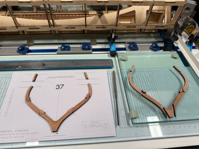
My technique is to attach the futtocks to the paper plan using paper glue. For me, the best way is to have three copies of each frame plan. Use one copy to make frame "A" one copy to make frame "B" and the third copy to mate both half frames. I'll have to put some thought into how to best deal with the stagger and spacing. Each frame will need lots of sanding and preparation before assembly and after assembly. At least for me, I think it will take at least 2-3 days per frame...Here are the parts for both of # 37 Half frames. The futtocks are spread over many sheets because of the differing thicknesses. They are clearly laser-labeled. Be real careful with the chocks, as they are futtock and frame specific.l
IMG_1585.jpeg
Frames "A" and "B" laid out. Futtocks not cleaned or prepared yet.

Alex R
 
Hello everyone.
Starting the frames today. They are complicated to say the least. I'm starting with the rearmost midship frame, # 37
What complicates the frame build is the different thicknesses of the futtocks, and the way the spaces are staggered. Each frame is made up of two half-frames. There are some inconsistencies in the instructions, which I can figure out, and only one frame plan sheet for each frame.
My technique is to attach the futtocks to the paper plan using paper glue. For me, the best way is to have three copies of each frame plan. Use one copy to make frame "A" one copy to make frame "B" and the third copy to mate both half frames. I'll have to put some thought into how to best deal with the stagger and spacing. Each frame will need lots of sanding and preparation before assembly and after assembly. At least for me, I think it will take at least 2-3 days per frame...Here are the parts for both of # 37 Half frames. The futtocks are spread over many sheets because of the differing thicknesses. They are clearly laser-labeled. Be real careful with the chocks, as they are futtock and frame specific.l
View attachment 513892
Frames "A" and "B" laid out. Futtocks not cleaned or prepared yet.

Alex R
Always a big moment, starting with the frames. Indeed complicated, Alex. But from what I can see the parts looks very nice.
Make sure the copies are exactly the same as the originals. Lay them on top of each other and hold them up to the light. A small difference can cause problems by aligning both together.
Looking forward to the result!
Regards, Peter
 
Last edited:
Ok, what's next ?

The building jig is complete and the completed keel structure is positioned inside the jig. Everything is tight and fits well.

My plan is to make the first and last midship frames, Frame # 1 and Frame # 37 and install them on the keel, then work alternating making frames from the bow and stern. This will take a long time!!!

Victor, any problems with my plan ?

Thanks

Alex R
View attachment 513512Due to

Good Day, Gentlemen. Due to my experience with the Hoy, I warmly reccomend to avoid jig floor as reference to determine heights of inner and outer structures. Always consider as "0" the slab surface wich you are working on. Regards. Alberto
 
Hello everyone.
Starting the frames today. They are complicated to say the least. I'm starting with the rearmost midship frame, # 37
What complicates the frame build is the different thicknesses of the futtocks, and the way the spaces are staggered. Each frame is made up of two half-frames. There are some inconsistencies in the instructions, which I can figure out, and only one frame plan sheet for each frame.
My technique is to attach the futtocks to the paper plan using paper glue. For me, the best way is to have three copies of each frame plan. Use one copy to make frame "A" one copy to make frame "B" and the third copy to mate both half frames. I'll have to put some thought into how to best deal with the stagger and spacing. Each frame will need lots of sanding and preparation before assembly and after assembly. At least for me, I think it will take at least 2-3 days per frame...Here are the parts for both of # 37 Half frames. The futtocks are spread over many sheets because of the differing thicknesses. They are clearly laser-labeled. Be real careful with the chocks, as they are futtock and frame specific.l
View attachment 513892
Frames "A" and "B" laid out. Futtocks not cleaned or prepared yet.

Alex R
Awesome Alex. Very cool looking frames. From what I can see they are appear very accurate. Are you going to nail these? Cheers Grant
 
Hello everyone.
Starting the frames today. They are complicated to say the least. I'm starting with the rearmost midship frame, # 37
What complicates the frame build is the different thicknesses of the futtocks, and the way the spaces are staggered. Each frame is made up of two half-frames. There are some inconsistencies in the instructions, which I can figure out, and only one frame plan sheet for each frame.
My technique is to attach the futtocks to the paper plan using paper glue. For me, the best way is to have three copies of each frame plan. Use one copy to make frame "A" one copy to make frame "B" and the third copy to mate both half frames. I'll have to put some thought into how to best deal with the stagger and spacing. Each frame will need lots of sanding and preparation before assembly and after assembly. At least for me, I think it will take at least 2-3 days per frame...Here are the parts for both of # 37 Half frames. The futtocks are spread over many sheets because of the differing thicknesses. They are clearly laser-labeled. Be real careful with the chocks, as they are futtock and frame specific.l
View attachment 513892
Frames "A" and "B" laid out. Futtocks not cleaned or prepared yet.

Alex R
I'm right here with ya except for some finishing touches on the keel. :) Again, you might watch the video that Modelship Dockyard did on the 1/96 scale to help explain the stagger and how to build them. I believe it is the #3 video you want for this. I'm only going to use the single original copy placed under a sheet of glass to build mine. :)
 
I'm right here with ya except for some finishing touches on the keel. :) Again, you might watch the video that Modelship Dockyard did on the 1/96 scale to help explain the stagger and how to build them. I believe it is the #3 video you want for this. I'm only going to use the single original copy placed under a sheet of glass to build mine. :)

Jeff,

Thanks, great suggestion. I'll watch the video today for sure.

My understanding is that frame "B" aligns with the solid line on the frame plan, and Frame "A" aligns with the dotted line. The two frames are glued together with the laser-printed (bevel indicator line ) facing outwards. In the center-most full frames, half frames A" and "B" are almost exactly on top of each other; but as the frames approach the stern and the bow, the position of the two half frames relative to each other begins to diverge..like astigmatism...

A question I have: for a stern frame (like # 37) when making half-frame "A" on the dotted line, do I lay the futtocks printed-side down, or printed-side up ?
In a frame with straight sides, no stagger, it wouldn't make any difference, (one just flips the frame over to glue it back to back to half-frame "B") but if the thickness of the futtocks differs, then spacing would be different depending on which side down the frames were constructed.. kinda complicated to explain....I'll go watch the video. I'll watch video, think, think, think, print some plan sheets, and clean up char today. Once I get the frame-making sequence, subsequent frames will go a little faster. I hope to get it right, but if not, I know you guys will set me straight. I'll send pics before any critical phase.

Thanks a lot !

Alex R
 
Awesome Alex. Very cool looking frames. From what I can see they are appear very accurate. Are you going to nail these? Cheers Grant
Grant,

Still a ways away, but yes, I plan to tree-nail the frames after they are glued-up.
I'll research, but I'm sure Allan will tell me what materials to use where ( iron bolts, wood trunnels a mixture? locations ?).

Thanks,

Alex R
 
Back
Top