Alex, I'm watching your build up here in Conroe and enjoying your dialog with Jeff, Allan and Russ. Have fun, Magic Mike
-

Win a Free Custom Engraved Brass Coin!!!
As a way to introduce our brass coins to the community, we will raffle off a free coin during the month of August. Follow link ABOVE for instructions for entering.
- Home
- Forums
- Ships of Scale Group Builds and Projects
- Modelship Dockyard PoF HMS Enterprize 1774 - 1/48
You are using an out of date browser. It may not display this or other websites correctly.
You should upgrade or use an alternative browser.
You should upgrade or use an alternative browser.
Hi Alex. Found the new Group Build and your build-log. Set my chair and follow it with great interest.
Regards, Peter
Regards, Peter
So far, the joinery with the graphite-laced yellow glue is strong, but the color is more grey than black, and I don't want to add more graphite to it; I will try the art paper sometime later on this kit. I see you have a T-track table...and you are using it. Do you like it ? so far, I love mine-very practical. Is your kit the CAF Enterprize? mine is the Dockyards' 1:48..Enterprize. Your stem is of a different construction, but similar shape, to mine. Nice joinery.FWIW, I have always "suspected" the graphite powder may weaken the yellow titebond from test pieces I ran tests on. My end result is using a very porous black art paper between joints. when glued, it is quite thin, and yields a strong joint, IMHO, quite realistic. The big plus..... when hit with glue, both surfaces, just enough to fill any tiny void giving nice finish. When dry, very easy to simply chisel away from wood.View attachment 511662View attachment 511664
That said, for this project, I have finished keel, bow, transom using nothing and joinery seems realistic here as well/ all pieces here where cut scratch from stock.
That said, I have been a lurker here for some time.....great forum and looking forward to following everyones progress on this fine kit.
Tim
AR
Thanks Mike,Alex, I'm watching your build up here in Conroe and enjoying your dialog with Jeff, Allan and Russ. Have fun, Magic Mike
Welcome, please watch and comment.
One of my best friends, Dr. Al Heilman, is a retired orthopedic surgeon who is now a really talented Artist in various media and also a gifted writer., He posts morning pictures of the lake and its incredible colors. What beauty.
Alex R
Welcome Peter. It is turning out to be a great group. Glad u are doing us.Hi Alex. Found the new Group Build and your build-log. Set my chair and follow it with great interest.
Regards, Peter
Alex R
Today and tomorrow: stem rabbet, and sanding down breakwater and stem apron. I decided to cut the rabbet by hand using gouges and chisels. Before cutting the rabbet, I'll sand the cutwater and stem apron, then glue all the stem pieces together, and,finally, cut the rabbet. The rabbet that runs up the stem will not be a continuous groove; rather, it will not be cut in the sections where the butt end of the wales meet the stern ( I sent Allan a PM about this-lets see what he says,.
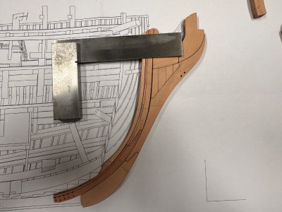
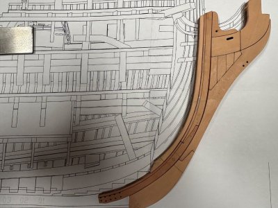
Marking where the wales meet the stem Areas without rabbet penciled in.
Upper apron assembly not glued yet.
Alex R


Marking where the wales meet the stem Areas without rabbet penciled in.
Upper apron assembly not glued yet.
Alex R
Last edited:
Sorry for the confusion, the T-track images are of my scratch Euryalus, only to show the paper joinery. If you have an art supply, this paper is a very loose, porous weave, you can literally pull it apart , but it compresses and gives nice result.So far, the joinery with the graphite-laced yellow glue is strong, but the color is more grey than black, and I don't want to add more graphite to it; I will try the art paper sometime later on this kit. I see you have a T-track table...and you are using it. Do you like it ? so far, I love mine-very practical. Is your kit the CAF Enterprize? mine is the Dockyards' 1:48..Enterprize. Your stem is of a different construction, but similar shape, to mine. Nice joinery.
AR
Mine is Dockyards and will go only with their jig resting on a thick melamine work surface. Have built a few frames, as of yet not glued to keel and it works quite well alone.
The Euryalus is framed out but in all boxwood the sanding was exhausting and I put it up for now under plastic. Framed and planked a scratch Confederacy, also on hold, but I hope to push through to finish on the 1/48 Enterprize
Well, since you are also building Dockyards' 1:48 Enterprize, you should start your build page in this area, and show us pictures of your work. Join us, we'll be saving a dry dock in the shipyard for you. All you have to do is go to the SOS group builds and projects area and start your build thread.Sorry for the confusion, the T-track images are of my scratch Euryalus, only to show the paper joinery. If you have an art supply, this paper is a very loose, porous weave, you can literally pull it apart , but it compresses and gives nice result.
Mine is Dockyards and will go only with their jig resting on a thick melamine work surface. Have built a few frames, as of yet not glued to keel and it works quite well alone.
The Euryalus is framed out but in all boxwood the sanding was exhausting and I put it up for now under plastic. Framed and planked a scratch Confederacy, also on hold, but I hope to push through to finish on the 1/48 Enterprize
Alex R
Good morning Alex. Wow this looks like a cool kit. All you guys on this group are like pioneers with this MD kit. Going to be super fun with plenty sharing of ideas and suggestions. You are off to a great start. Cheers Grant
PS : I feel like the lonely lamb lost in the wilderness with my CAF version….

 .
.
PS : I feel like the lonely lamb lost in the wilderness with my CAF version….


 .
.Sorry you feel like a lost lamb. You are welcome to hang out here.Good morning Alex. Wow this looks like a cool kit. All you guys on this group are like pioneers with this MD kit. Going to be super fun with plenty sharing of ideas and suggestions. You are off to a great start. Cheers Grant
PS : I feel like the lonely lamb lost in the wilderness with my CAF version….

.

Well, I guess you already are. LOL
I was looking ahead in the instructions tonight and it looks like we will be working on frames for about 20 years!
Of course, we still have a ways to go before we get to work on them.
Keel structure is almost finished. Needs more sanding and gap filling.
Last night and this AM:
1) I narrowed down the forward edge of the knee of the head (cutwater) to 4.5 mm (keel width is 8mm) from the top down to the junction with gripe. Too far ? (sorry, cannot undo) Not far enough ? Could narrow the gripe all the way to the junction with the keel - what do you guys think ?
2) Sanded and narrowed the Apron to 3mm at the bottom-to accept the piece with steps ( name?) where the hawse frames butt against the keel structure. I'll glue this to the st-em structure when I mate it to the keel.
3) Have not cut out rabbet yet. Still what gouges to use to make the correct cross section and weather it is comntinous up the stem or not.
4) plan to sand down and join halves of keel today (maybe).

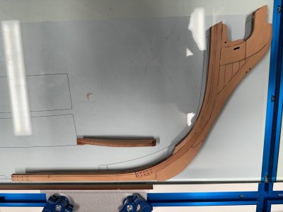

Rabet cross section and stem nomenclature (Longridge-Anatomy of Nelson's ships). My stem structure and the apron filed down.
Alex R
Last night and this AM:
1) I narrowed down the forward edge of the knee of the head (cutwater) to 4.5 mm (keel width is 8mm) from the top down to the junction with gripe. Too far ? (sorry, cannot undo) Not far enough ? Could narrow the gripe all the way to the junction with the keel - what do you guys think ?
2) Sanded and narrowed the Apron to 3mm at the bottom-to accept the piece with steps ( name?) where the hawse frames butt against the keel structure. I'll glue this to the st-em structure when I mate it to the keel.
3) Have not cut out rabbet yet. Still what gouges to use to make the correct cross section and weather it is comntinous up the stem or not.
4) plan to sand down and join halves of keel today (maybe).


Rabet cross section and stem nomenclature (Longridge-Anatomy of Nelson's ships). My stem structure and the apron filed down.
Alex R
- Joined
- Mar 22, 2024
- Messages
- 396
- Points
- 168

You are quite right. Graphite has a laminar flake structure at heart, and the laminations on the graphite will fail before the glue. Carbon Black, or black powder paint would be a better choice.FWIW, I have always "suspected" the graphite powder may weaken the yellow titebond from test pieces I ran tests on.
- Joined
- Jan 10, 2022
- Messages
- 856
- Points
- 403

Agree JeffLooking good !! If you look at the partss E1-11 & E1-12, as well as E2-26 and E2-27, there is a laser burn line on the inside edge. That is where the rabbet goes. It also follows along the keel as well.Personally, I think it would be easier to cut the rabbet prior to gluing. That is how I plan to tackle it.
Ok, keel structure is finished, and I started on the jig last PM.
I decided not to "staple" the false keel in.
The jig is a construction project in itself; the plywood is flat and cut accurately, needing only minimal sanding of joints. The instruction diagrams are clear, but you have to figure out the installation sequence on your own.
The jig is made in two sections "A" and "B", that are later joined together., I dry/fit them first, and then a thin line of Cyano at the joints. The jig(s) feel stable and sturdy. Putting in the diagonal supports B5 and A5 was tricky, I was lucky/careful not to break anything. I was wondering if it wouldn't have been easier to install parts B6 and A6 AFTER the diagonal supports B5 and A5. I figured out -daahh- that all "A" parts belong to the After end-stern end of the jig, and all parts "B" to the Bow.
TBC
Alex Rosas
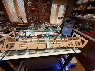
Rosas shipyard: Building jig in two parts. Completed keel in the background.
I decided not to "staple" the false keel in.
The jig is a construction project in itself; the plywood is flat and cut accurately, needing only minimal sanding of joints. The instruction diagrams are clear, but you have to figure out the installation sequence on your own.
The jig is made in two sections "A" and "B", that are later joined together., I dry/fit them first, and then a thin line of Cyano at the joints. The jig(s) feel stable and sturdy. Putting in the diagonal supports B5 and A5 was tricky, I was lucky/careful not to break anything. I was wondering if it wouldn't have been easier to install parts B6 and A6 AFTER the diagonal supports B5 and A5. I figured out -daahh- that all "A" parts belong to the After end-stern end of the jig, and all parts "B" to the Bow.
TBC
Alex Rosas

Rosas shipyard: Building jig in two parts. Completed keel in the background.
Last edited:
The keel structure is now in the building jig !
A few comments for the build group:
If you haven't built the jig-
1)keep the parts so that the layered number is towards the bow...Thyer external surfaces of parts B6 and A6 should be smooth, no parts should protrude.
2)in step # 3 -platform, parts A 12 and B 12 go at the top. The build drawings show part A 11 in at the top, bow side. The part number is wrong. The part is A 12. (B 12 plus A 12 are the parts that make up the top of the side bands.)
3) The bow keel structure fits well in the front, but there is a 9/64 " gap between the sternpost and the stern support on the jig. I don't think I missed a piece, but I'll check. If anybody knows (Victor) or is at this stage (Corsair) ? Help..

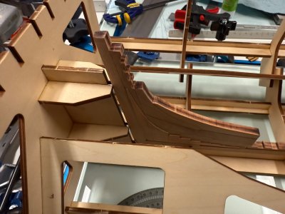

Full keel in jig. 9/64" gap between sternpost and jig stern support. (why?) Bow deadwood fits well
Thanks
Alex R
.
A few comments for the build group:
If you haven't built the jig-
1)keep the parts so that the layered number is towards the bow...Thyer external surfaces of parts B6 and A6 should be smooth, no parts should protrude.
2)in step # 3 -platform, parts A 12 and B 12 go at the top. The build drawings show part A 11 in at the top, bow side. The part number is wrong. The part is A 12. (B 12 plus A 12 are the parts that make up the top of the side bands.)
3) The bow keel structure fits well in the front, but there is a 9/64 " gap between the sternpost and the stern support on the jig. I don't think I missed a piece, but I'll check. If anybody knows (Victor) or is at this stage (Corsair) ? Help..


Full keel in jig. 9/64" gap between sternpost and jig stern support. (why?) Bow deadwood fits well
Thanks
Alex R
.
A big step! Congratulations!
Not a huge deal, but once I sanded the sternpost to proper dimension….with same gap, I carefully widened the gap to fit stern snugly and the entire keel assembly snapped down snugly with no bind and it fit tight against vertical support.The keel structure is now in the building jig !
A few comments for the build group:
If you haven't built the jig-
1)keep the parts so that the layered number is towards the bow...Thyer external surfaces of parts B6 and A6 should be smooth, no parts should protrude.
2)in step # 3 -platform, parts A 12 and B 12 go at the top. The build drawings show part A 11 in at the top, bow side. The part number is wrong. The part is A 12. (B 12 plus A 12 are the parts that make up the top of the side bands.)
3) The bow keel structure fits well in the front, but there is a 9/64 " gap between the sternpost and the stern support on the jig. I don't think I missed a piece, but I'll check. If anybody knows (Victor) or is at this stage (Corsair) ? Help..
View attachment 513253View attachment 513254View attachment 513255
Full keel in jig. 9/64" gap between sternpost and jig stern support. (why?) Bow deadwood fits well
Thanks
Alex R
.
I am now through 11 frames, all only dry fit. They seem to fit, space very well and I carefully bevel with spindle sander barely off lines for interior/exterior surfaces to allow for finish sanding. You need care with proper support pieces glued to top between frame pairs to ensure snug, proper fit in jig.
Doing this gets you about 90%.
I have sanded, test fit top/bottom gunport pieces just dry fit but since they are thinner than frame tops, trying to figure when I do fit them to align them to the outside frame surface, or inside, or middle and then sand frames to match.
Victor……any advise?
P.S. going back to the extensive “new kit” forum, it appears that the top/ bottom port sills are noticeably different from kit supplied, particularly the top sill which is not angle cut into frame. I wonder if it is better to simply custom make them frame width which will not be very difficult.
Any thoughts?
Last edited:
Thanks Doc...
I jlooked at the build carefully and I did not miss a piece or made a mistake ( not know what I don't know) just sanded down a piece of spare wood to fill the space between the jig stern support and the sternpost. I don't like gaps, and this piece will just add support
to the keel. The second picture shows the sternpost and the new support piece from above. The sternpost is tapered and sanded down to 3mm.
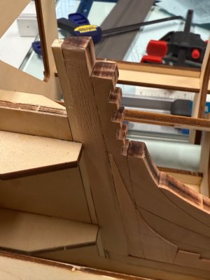
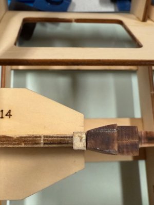
Cheers
ALEX R
I jlooked at the build carefully and I did not miss a piece or made a mistake ( not know what I don't know) just sanded down a piece of spare wood to fill the space between the jig stern support and the sternpost. I don't like gaps, and this piece will just add support
to the keel. The second picture shows the sternpost and the new support piece from above. The sternpost is tapered and sanded down to 3mm.


Cheers
ALEX R
Do you sleep ? Do you have children laboring on your ship 24-7 _. You are moving FAST....___Congratulations..Not a huge deal, but once I sanded the sternpost to proper dimension….with same gap, I carefully widened the gap to fit stern snugly and the entire keel assembly snapped down snugly with no bind and it fit tight against vertical support.
I am now through 11 frames, all only dry fit. They seem to fit, space very well and I carefully bevel with spindle sander barely off interior/exterior surfaces to allow for finish sanding. You need care with proper support pieces glued to top between frame pairs to ensure snug, proper fit in jig.
Doing this gets you about 90%.
I have sanded, test fit top/bottom gunport pieces just dry fit but since they are thinner than frame tops, trying to figure when I do fit them to align them to the outside frame surface, or inside, or middle and then sand frames to match.
Victor……any advise?
AR
Worth a mention/ question, with your solution keeping the post somewhat away from the jig, will it, perhaps, throw the geometry off slightly when setting up the upper structure? This is what I scratched my head about and ultimately decided to insure the post was tight against jig.Thanks Doc...
I jlooked at the build carefully and I did not miss a piece or made a mistake ( not know what I don't know) just sanded down a piece of spare wood to fill the space between the jig stern support and the sternpost. I don't like gaps, and this piece will just add support
to the keel. The second picture shows the sternpost and the new support piece from above. The sternpost is tapered and sanded down to 3mm.
View attachment 513266View attachment 513267
Cheers
ALEX R
All to be discovered down the road, but I offer up my thought process.


