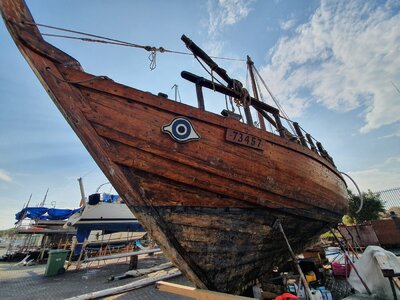
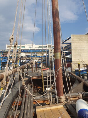
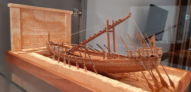
Ancient Phoenician Trade Boat 1500-1400 BC Build Log PT-2

Thinking ahead about the best, at reasonable cost of course, what can anyone recommend that I use to cut and shape these frames which are only about 1/8" wide and would be sensitive to grain fracturing when being fared. My assumption would be some type of thin plywood with both finish faces of a species that will take a brownish tone when oiled or lightly stained.
Same question for species for hull and deck planking, again, no paint finishes.
My port has an open dock for all arriving suggestions. Thanks. Rich
Greetings Rich and Happy Holidays! Bottle
I wouldn't recommend plywood for frames for multiple reasons. Plywood is a multilayered veneer hot pressed with glue between the layers.
  • Bad quality plywood will chip in places where glue is not presented\well set
  • It is very difficult to fair-very thin (1/8) ply because of the cross-grained structure of the ply. Thin pieces will snap\brake easily
  • even the highest grade ply will not look good on the end-frame, it will show the multilayered structure (different color)
  • some grades of plywood will be impossible to stain because of the type of glue in use between the layers
You can utilize Poplar wood for the frames and Walnut for the keel structure, it should be a much better choice than ply, IMHO. However. if you still desire to use plywood instead of actual timber, use Baltic plywood with the highest (expensive) grade, preferably A or B. They use a good veneer and made a very smooth finish.
 
Not sure which is more ancient, the vessel under design and build, or the tools and methods to do the drawing.
Dr. Mike (Mikhail Bezverhniy) a very famous Russian ship modeler still uses the "old school' technicks\tools when it comes to verifying drafts.
 
Greetings Rich and Happy Holidays! Bottle
I wouldn't recommend plywood for frames for multiple reasons. Plywood is a multilayered veneer hot pressed with glue between the layers.
  • Bad quality plywood will chip in places where glue is not presented\well set
  • It is very difficult to fair-very thin (1/8) ply because of the cross-grained structure of the ply. Thin pieces will snap\brake easily
  • even the highest grade ply will not look good on the end-frame, it will show the multilayered structure (different color)
  • some grades of plywood will be impossible to stain because of the type of glue in use between the layers
You can utilize Poplar wood for the frames and Walnut for the keel structure, it should be a much better choice than ply, IMHO. However. if you still desire to use plywood instead of actual timber, use Baltic plywood with the highest (expensive) grade, preferably A or B. They use a good veneer and made a very smooth finish.
I went back into my scrap pile from the BN and Kyrenia kits to find the remnant pieces:
BN laser cut plywood was 3/16" 3-ply for the bulkheads
Kyrenia laser cut plywood was 5/64" 3-ply for frames

How fragile are Poplar and Walnut to grain fracturing?

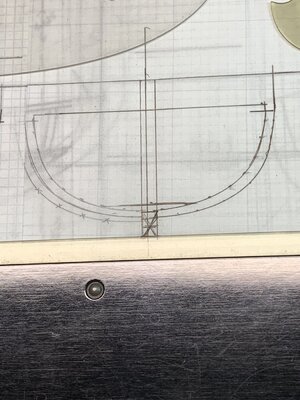
That is my concern with cutting out the narrow frames for the trade ship where the keel cutout extends well past the face width of the frames so I added a horizontal bridge over the top of the keel cutout. You can see that in the photo below.

Going back to those the "face width" is ~4mm, the keel cutout width is ~5mm, and the distance above that cutout and the top of the bridging piece leaves ~5mm . That is where I think that the breakage may be most likely to happen.
Trade Boat First Two Frames MIdships.jpg
I don't know how to draw annotation lines onto this image to clarify where the dimensions are located so you will have to bounce back and forth between my text and the photo for clarification.
Now, back to the garage drafting table to trace/draw a few more frames pieces before my hands get too cold. Rich
 
I went back into my scrap pile from the BN and Kyrenia kits to find the remnant pieces:
BN laser cut plywood was 3/16" 3-ply for the bulkheads
Kyrenia laser cut plywood was 5/64" 3-ply for frames

How fragile are Poplar and Walnut to grain fracturing?

That is my concern with cutting out the narrow frames for the trade ship where the keel cutout extends well past the face width of the frames so I added a horizontal bridge over the top of the keel cutout. You can see that in the photo below.

Going back to those the "face width" is ~4mm, the keel cutout width is ~5mm, and the distance above that cutout and the top of the bridging piece leaves ~5mm . That is where I think that the breakage may be most likely to happen.
Hello Rich, before we will continue the discussion on the wood properties, are you making frames or bulkheads? You mentioned the BN laser cut plywood bulkheads. For bulkheads, plywood is acceptable material for frames not so.
 
Hello Rich, before we will continue the discussion on the wood properties, are you making frames or bulkheads? You mentioned the BN laser cut plywood bulkheads. For bulkheads, plywood is acceptable material for frames not so.
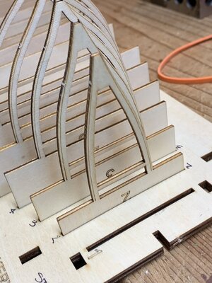
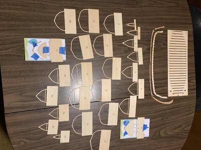
My terminology is not clear so I will attach a photo of the "frames" parts from the Kyrenia kit with the others on a table. They are a D shape with a cutout area forming the interior faces of the frame. This is what I am drawing and anticipate using, set on a strongback without cutouts as was in the Kyrenia kit jig on the right of the keel:Kyrena Loose Frames in Jig.jpg
Kyrenai Structure and Jig.jpg

Somehow the two photos exchanged positions as I wanted the table view first and then those "frames" pieces in the jig slots. Just afterwards to the photo I inserted spacing blocking pieces flush on the jig to secure the uprights. I will do the same with the trade boat "frames" but without slots in the strong-back.

These are the plywood pieces 5/64" thick. The Keel was placed in the slots atop the frames which stabilized and provided some strength for careful fairing which is my intent, if valid, for the trade ship.
Rich
 
These are the plywood pieces 5/64" thick. The Keel was placed in the slots atop the frames which stabilized and provided some strength for careful fairing which is my intent, if valid, for the trade ship.
Got it, Rich. These are not real frames the way we would build the POF (Plank On Frame) model. Those are bulkheads and can be made out of play.
Good quality plywood made by company 'Midwest'. Check out their products, they have a variety of sizes and sicknesses.

 
Got it, Rich. These are not real frames the way we would build the POF (Plank On Frame) model. Those are bulkheads and can be made out of play.
Good quality plywood made by company 'Midwest'. Check out their products, they have a variety of sizes and sicknesses.

Thank you Jim for the lead that I will follow.
In trying to draw the lines for one more bulkheadforward from my prior midships pair, when verifying between the sheer plan for what should vertically correspond from the half hull plan above I quickly detectd that they are in conflict and do not agree with what was printed for the same curves of the body plan (lower right corner drawing). It seems that the curves supposedly those at the five major stations along the hull do not agree and are more of a cartoonist's creation for visual effect than accuracy. Without a true set of half hull lines I am not sure now how to draft a coordinated set of bulkheads.

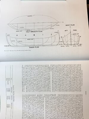
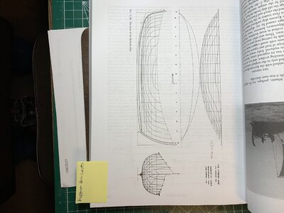
As an introductory visualization of lines and sections I look at a figure of such drafting from J. Steffy;s book Wooden SHip Building and the Interpretation of Shipwrecks
Plan Views Names.jpg
This figure provides the terminology and simplified illustration of the various lines. An example of a more complete set of lines is shown in those by Steffy of Kyrenia
Kyrenia Plans View Hull Lines.jpg
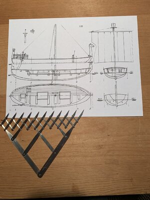
In the most cursory comparison it it obvious that the Trade Ship plan drawings omit the number and necessary lnes with which to draw up a compliment of bulkheads. 8.5 x 11 print of Trade Boat Plan Sheet with dividers.jpg
Looking at the Body plan we find only lines/curves for stations 1, 2, 3, 4 and no diagonals; nor are the same lines clearly presented on the half hull view. The sheet drawings look OK until critical projections are made.

I think that I will have to design my own hull from what I have and can find to loft a schematic set of bulkheads in pasteboard then place some trial strakes (full length planks or wales) to find out how to refine the bulkheads' lines accordingly. For my limited knowledge and experience this has become much more involved and challenging to produce a hull than I thought I was purchasing plans to use straight off. Only $9.99 spent to Best Ship Models..

At least I can state that there were no Early Bronze age and extremely few shipwrecks for the archaeologists to recreate the recoverable and hypothetical hull and ship so I am in similar waters of conjecture . . . setting aside the artistic iconograhic images from old pottery and monuments.

This is a side of ship modeling that I believe most SoS model builders are not engaged with or interested in starting from "blank paper" and pencil (or CAD) as their hobby, much less a step along the way to actually building something material with their hands.
 
Starting a somewhat redundant log from an earlier one that morphed into the Kyrenia model in it's own log.
I will open with the photos of the single sheet that I will enlarge and work up the hull lines to create the mold/frames from there in this scratch build.
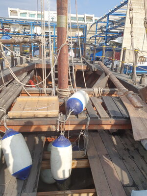
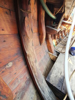
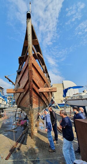
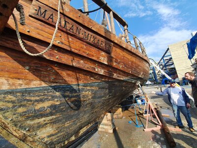
View attachment 276699View attachment 276700View attachment 276701
With only this sparse information I will embark on a voyage into the foggy dew drifting atop the waves of the unknown, relying upon the research papers and Kyrenia model experience to amplify the voids. Rich (PT-2)
I do so enjoy your poetic descriptions!
 
Starting a somewhat redundant log from an earlier one that morphed into the Kyrenia model in it's own log.
I will open with the photos of the single sheet that I will enlarge and work up the hull lines to create the mold/frames from there in this scratch build.
View attachment 276699View attachment 276700View attachment 276701
With only this sparse information I will embark on a voyage into the foggy dew drifting atop the waves of the unknown, relying upon the research papers and Kyrenia model experience to amplify the voids. Rich (PT-2)
Have a nice Christmas, Rich. And again a very interesting project. I am with you in spirit ;-)
 
Rich following with great interest, as I have always wanted to learn how to develop ship frames from drawings of boats. You have peaked my interest again to return to that study. As for drafting I also sent my working career in the engineering field doing piping design and drafting.
 
Have a nice Christmas, Rich. And again a very interesting project. I am with you in spirit ;-)
Thank you for the Christmas present of the link and detailed photos. I had previously read an academic paper comparing the wood and construction of both wrecks. Your photos of the reconstruction add to my data bank of ships of the 5thc BC. Much later than the trade boat that I am trying to work out for hull lines.
As stated above there are conflicts between the plan drawings so I went back to the beginning using the repositioned drawings to cast new lines using both the compas and graphic (45 degree turn from horizontal to vertical) offset points. Without additional diagonals on the hull plan and the corresponding half hull lines The curves become more a work of visual art and estimation. Here are a couple of photos showing my restart.
First is one showing the graphic 45 degree turn line between the half breadth (full actually) Graphic check of compass cast body plan lines.jpg plan and body plan:
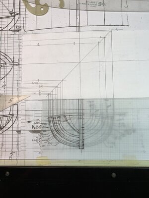
I am able to directly draw the horizontal points from the shear plan on the left to the body plan for those vertical positions.
Here are the full set of major stations from both the stern and stem views on the body plan.
Redrawn Hull Body Plan Lines.jpg
I will place another small piece of semi-transparent drafting paper over the hull plan and trace one hull line, flip it over and trace the other corresponding line, and then give some width to the "frame" at that station. . . . over and over until I have this set completed and use those to cut a set of cardboard bulkhead frames to see how they fair out. This will also give me an idea of the need of intervening bulkhead frames smoothing the curves of the planking strakes stem to stern.

It is interesting for me to see some jumps or gaps between the lines which I wold not have suspected at first viewing of the half body plan from above. I would have thought that there would have been a more regular spacing between these curves. These strange spacings are most apparent in the aft stations but rechecking so far at this point says this is correct. . . being Swedish I am still not convinced that there is not an error in take-off somewhere. . . maybe in the ghost of a drunken sailor singing and staggering along the dockside of my drafting table.

When all is fared out I will make a decision on planking widths and the number required to mark those onto the edges of the bulkhead frames.

With Christmas in memory now, we can all look forward to a hopefully good New 2022 Year. Peace, Health, and Happiness to all! Rich (PT-2)
 
Rich following with great interest, as I have always wanted to learn how to develop ship frames from drawings of boats. You have peaked my interest again to return to that study. As for drafting I also sent my working career in the engineering field doing piping design and drafting.
If we are fortunate enough to have or receive a table of offsets then it just becomes the tedious task of marking those off to cast the lines. For the archaeological reconstructionist they have the actual members to measure and create those offsets. In my limited information status I must rely on assumptions or if willing to give it time and effort to carve out a balsa hull, shaped to desired form, and then measure and take off the dimensions creating a table leading back to drafting. . . . at least as assumed from my more limited architectural drawing career and not nautical or aeronautical curves demands. Thanks for your interest and any ideas that may come to mind. Rich
 
Basic hull draftmanship. Gotta love it. Once you're done making frame lines, you can cut out some frames and make a skeleton using the keel, plank it, then remove the frames. That way you won't have to carve a solid wood hull, but instead you have a hollow one which you can add historically accurate reinforcement frames, ribs and other internals. You end up with a historically accurate looking hull, inside and outside from scratch. You'll have a custom built model with outstanding features, PT-2!

Check out this Egyptian ship built from scratch by Helmuht Shrader on the MSW forum: LINK

1640488661050.png
 
Basic hull draftmanship. Gotta love it. Once you're done making frame lines, you can cut out some frames and make a skeleton using the keel, plank it, then remove the frames. That way you won't have to carve a solid wood hull, but instead you have a hollow one which you can add historically accurate reinforcement frames, ribs and other internals. You end up with a historically accurate looking hull, inside and outside from scratch. You'll have a custom built model with outstanding features, PT-2!

Check out this Egyptian ship built from scratch by Helmuht Shrader on the MSW forum: LINK

View attachment 278017
I remember seeing the design and construction of the diorama. The entire project was excellently executed. Thanks for giving me a fresh look at it once again. Rich
 
I remember seeing the design and construction of the diorama. The entire project was excellently executed. Thanks for giving me a fresh look at it once again. Rich
From a scan of the build log from the LINK I see that he had a set of hull lines from a pdf to transfer into AutoCad at his 1:32" scale and then with the carving resource of a CNC machine to a lot of precise repetitive tooling of the wood. His technical skills are far above my own and resulted in an outstanding model and diorama. I will have to follow my own tack from an almost nothing start of lines and method ically, with likely variations in symmetry, work through this trade boat.
I noticed that I had previously downloaded and read some of the papers that he used in his understanding of the boat as well as the combined mortise and tenon with woven construction which he so well executed. It was and is a bar to be emulated as feasible. Rich
 
Starting a somewhat redundant log from an earlier one that morphed into the Kyrenia model in it's own log.
I will open with the photos of the single sheet that I will enlarge and work up the hull lines to create the mold/frames from there in this scratch build.
View attachment 276699View attachment 276700View attachment 276701
With only this sparse information I will embark on a voyage into the foggy dew drifting atop the waves of the unknown, relying upon the research papers and Kyrenia model experience to amplify the voids. Rich (PT-2)
Hi Rich,
Interesting project, that I am happy to tag along with even if I am a little late.
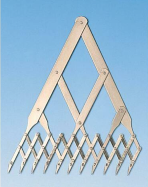
That is one nice looking old school scale rule and a marking device I have not seen before.

Cheers,
Stephen.
 
Hi Rich,
Interesting project, that I am happy to tag along with even if I am a little late.
That is one nice looking old school scale rule and a marking device I have not seen before.

Cheers,
Stephen.
I also have one of those scaling dividers. Very fast when having to plot multiple points across a known span length. You can use them for marking the locations of vertical seams in sails or reefing points quickly, or the locations of rail bannisters on the gunwales. It's an old school tool for draftsmen. These days they are scarce and expensive, and thus probably not worth the cost since you can get by with a ruler. This is the cheapest one I found on eBay: LINK

1640503504592.png
 
From a scan of the build log from the LINK I see that he had a set of hull lines from a pdf to transfer into AutoCad at his 1:32" scale and then with the carving resource of a CNC machine to a lot of precise repetitive tooling of the wood. His technical skills are far above my own and resulted in an outstanding model and diorama. I will have to follow my own tack from an almost nothing start of lines and method ically, with likely variations in symmetry, work through this trade boat.
I noticed that I had previously downloaded and read some of the papers that he used in his understanding of the boat as well as the combined mortise and tenon with woven construction which he so well executed. It was and is a bar to be emulated as feasible. Rich
Hi Rich,
I must praise you for your persistence, I think I would have walked away from this endeavor by now.
IMHO I would say that any reconstruction would have lashings of "best guess" involved.
The thing that I wonder about is how they were built, with what tools and materials and I would tend to think there is a need to think outside the box and resist the urge to apply more modern boat building ideas, I say this more as a thought bubble than any criticism of your work.
Keep up the good work.

Cheers,
Stephen.
 
I also have one of those scaling dividers. Very fast when having to plot multiple points across a known span length. You can use them for marking the locations of vertical seams in sails or reefing points quickly, or the locations of rail bannisters on the gunwales. It's an old school tool for draftsmen. These days they are scarce and expensive, and thus probably not worth the cost since you can get by with a ruler. This is the cheapest one I found on eBay: LINK

View attachment 278025
Thanks Kurt,
You are quite right they are expensive, I won't be rushing out to buy some.
I do have a proportional dividers that are very useful at times.

Cheers,
Stephen.
 
Back
Top