-

Win a Free Custom Engraved Brass Coin!!!
As a way to introduce our brass coins to the community, we will raffle off a free coin during the month of August. Follow link ABOVE for instructions for entering.
-

PRE-ORDER SHIPS IN SCALE TODAY!
The beloved Ships in Scale Magazine is back and charting a new course for 2026!
Discover new skills, new techniques, and new inspirations in every issue.
NOTE THAT OUR FIRST ISSUE WILL BE JAN/FEB 2026
You are using an out of date browser. It may not display this or other websites correctly.
You should upgrade or use an alternative browser.
You should upgrade or use an alternative browser.
Ancient Phoenician Trade Boat 1500-1400 BC Build Log PT-2
Hi Rich,The illuminated tracing box arrived, so now with a new set of technical pens and a small T-square, I can restart drawing the mold bulkheads in the comfort of my den/hobby room, and more able to assist my wife in her needs without calling me on the cell phone to come in from the garage. Rich
View attachment 282649
Looks like the light box will be a big help and being in a warm room an even bigger help.
Cheers,
Stephen.
- Joined
- Sep 3, 2021
- Messages
- 5,190
- Points
- 738

Good day Rich,
Just read through a couple of older posts.
Reading that you are working in your office/garage at near freezing temperatures raises my respect for your perseverance quite a couple of notches. I only have to do the initial wood removal in the garage, with temperatures in the mid forties, after that I can flee inside and use my hobby annex music room, heated.
On drawing your lines, also related to the temperatures you're working with, but also the humidity; for full-scale drawings we used stretch/shrink free sheets, I think we refered to it as Mylar. Can't remember if it was a brand name though.
The other transparent sheets we used showed a considerable amount of deviation, even on relatively small components. So we were only allowed these sheets for scaled drawings. If possible ánd affordable it might be worth the effort to use stretch/shrink free sheets, if you're not already using a similar material.
Johan
Years ago in our architectural office, before the advent of CAD, we went from vellum to mylar sheets and polymar drafting instead of graphite. As a very early format of what evolved into CAD layers, our sheets were punched along the top aligning with a flat pin bar where additional sheets were laid for drawing of specific elements looking through to the base plan drawing below. We could assembly numbers of related sheets to print a final composite in a large vacuum frame light table. All of that evolved into the layers of CAD files.Good day Rich,
Just read through a couple of older posts.
Reading that you are working in your office/garage at near freezing temperatures raises my respect for your perseverance quite a couple of notches. I only have to do the initial wood removal in the garage, with temperatures in the mid forties, after that I can flee inside and use my hobby annex music room, heated.
On drawing your lines, also related to the temperatures you're working with, but also the humidity; for full-scale drawings we used stretch/shrink free sheets, I think we refered to it as Mylar. Can't remember if it was a brand name though.
The other transparent sheets we used showed a considerable amount of deviation, even on relatively small components. So we were only allowed these sheets for scaled drawings. If possible ánd affordable it might be worth the effort to use stretch/shrink free sheets, if you're not already using a similar material.
Johan
My needs for a small model are quite modest and I forego the demands of precise linework knowing that everything will be filed/fared to the hull form.'
My latest efforts after some preliminary fairing has been to work on the keel, the rabbit for closing planks/garboard at the bottoms of the bulkheads, and rough carving of the Phoencian Hippos (horse head) ornamentation of the stem and tail on the stern rising portion. This is still loose set but will very soon need to be secured, without glue while the hull planking strakes are laid down with edge adhesion only and nothing bonding to the bulkheads.
Here are a few updating views:
The Hippos roughed out:
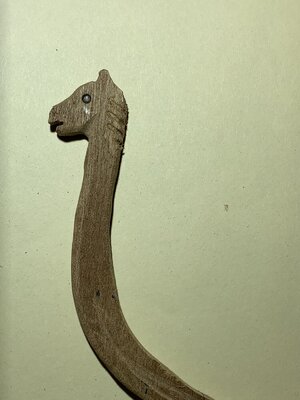
Then the full keel with scribed rabbit:
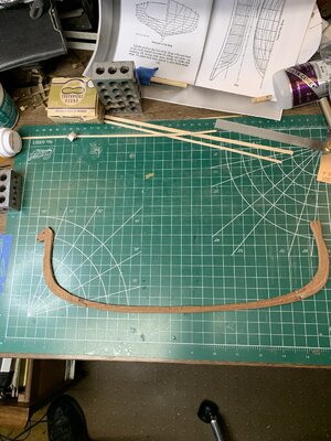
The two places where I broke it (twice) and made some repairs are evident. Most of those will be covered with the closing planks.
Next the loose set keel in the bulkheads:
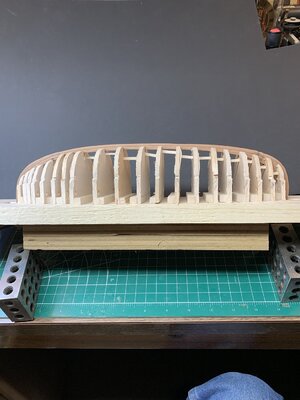
Some major attention and shims may be needed in the forward group of bulkheads. I had shimmed those previously but those came off in cutting out the keel notch.
Next a closer honest view of the stern keel area:
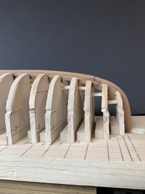
'and now the problem bow stem:
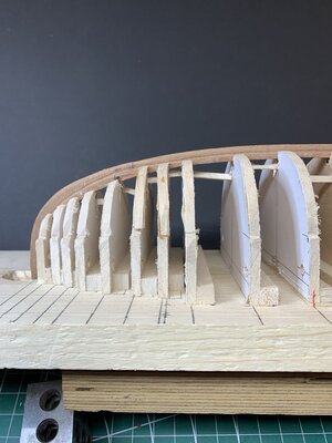
Oh well . . . .it is just a hobby to fill some of my time and not death and taxes!!! Rich
Hi Rich,
Making great progress on your interesting project.
One question, are you going to put something on the formers to prevent accidental gluing of planks to the formers.
Cheers,
Stephen.
Making great progress on your interesting project.
One question, are you going to put something on the formers to prevent accidental gluing of planks to the formers.
Cheers,
Stephen.
Wax paper or even plastic wrap from your kitchen wrapped over the entire framework would prevent the individual frames from sticking to the form.
A nice progress, Rich. With a beautiful carved Hippos head!
Regards, Peter
Regards, Peter
- Joined
- Sep 3, 2021
- Messages
- 5,190
- Points
- 738

It's a hobby, highly preferable over death and taxes. At least it gives me a lot more fun and satisfaction.Years ago in our architectural office, before the advent of CAD, we went from vellum to mylar sheets and polymar drafting instead of graphite. As a very early format of what evolved into CAD layers, our sheets were punched along the top aligning with a flat pin bar where additional sheets were laid for drawing of specific elements looking through to the base plan drawing below. We could assembly numbers of related sheets to print a final composite in a large vacuum frame light table. All of that evolved into the layers of CAD files.
My needs for a small model are quite modest and I forego the demands of precise linework knowing that everything will be filed/fared to the hull form.'
My latest efforts after some preliminary fairing has been to work on the keel, the rabbit for closing planks/garboard at the bottoms of the bulkheads, and rough carving of the Phoencian Hippos (horse head) ornamentation of the stem and tail on the stern rising portion. This is still loose set but will very soon need to be secured, without glue while the hull planking strakes are laid down with edge adhesion only and nothing bonding to the bulkheads.
Here are a few updating views:
The Hippos roughed out:
View attachment 290506
Then the full keel with scribed rabbit:
View attachment 290507
The two places where I broke it (twice) and made some repairs are evident. Most of those will be covered with the closing planks.
Next the loose set keel in the bulkheads:
View attachment 290512
Some major attention and shims may be needed in the forward group of bulkheads. I had shimmed those previously but those came off in cutting out the keel notch.
Next a closer honest view of the stern keel area:
View attachment 290513
'and now the problem bow stem:
View attachment 290514
Oh well . . . .it is just a hobby to fill some of my time and not death and taxes!!! Rich
Yes I have been considering that. The major need is in carefully placing the glue between the bulkheads/formers but that becomes problematic when they are very close together at each end.Hi Rich,
Making great progress on your interesting project.
One question, are you going to put something on the formers to prevent accidental gluing of planks to the formers.
Cheers,
Stephen.
It's a hobby, highly preferable over death and taxes. At least it gives me a lot more fun and satisfaction.
And the return is not lost or delayed in the mail. We do our own autits whch avoids penalties and interest fees. Rich
Wax paper or even plastic wrap from your kitchen wrapped over the entire framework would prevent the individual frames from sticking to the form.
My question about a full wrap which I also thought of is that I plan on using the small binder clips and rubber bands to hold each plank edge tightly in place and I don't think that I could do that with a kitchen wrap covering. It would show the overall hull form though so it is worth an experimental application.And the return is not lost or delayed in the mail. We do our own autits whch avoids penalties and interest fees. Rich
Decided to use 3/4 inch mylar tape along the edge of each bulkhead and cut the edges toward the bulkhead about 1/4" o.c. to then fold those to the face of the bulkhead on each side. Not original as I think that one of our Galilee modelers did the same thing.My question about a full wrap which I also thought of is that I plan on using the small binder clips and rubber bands to hold each plank edge tightly in place and I don't think that I could do that with a kitchen wrap covering. It would show the overall hull form though so it is worth an experimental application.
Here is one with one side clipped but not folded yet to match the opposite side:
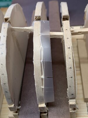
The loose paper pattern edge folds flat under the tape.
When the spaces were too narrow for my iris sizzor I used the point of a sharp No. 19 exacto for the cut and a clay sculpting tool to set and rub the segments in place.
Now with those done I have set the unglued keel with rubber bands to hold it in place while the planks will be secured into the stem and stern rabbits with CV for the first plank. When that is set I will apply the Titebond with a hypydermic sryringe on the edges between each bulkhead. The tape is just a safety factor life ring.
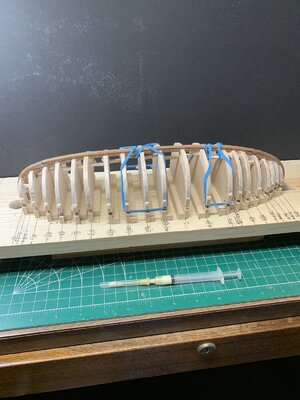
Except for the stem and stern anchorages things will be floating for a while until some of the edges begin to engage the keel sides forming the shell of the hull. The long rubber bands will become sacrificial when I need to get them out of the way a planks are added upward toward the keel.
Hopefully . . . the hull will lift off and out of the build board. We'll see about that later. Rich
- Joined
- Sep 3, 2021
- Messages
- 5,190
- Points
- 738

Is it not feasible to do a small test run, before you commit to this process?Decided to use 3/4 inch mylar tape along the edge of each bulkhead and cut the edges toward the bulkhead about 1/4" o.c. to then fold those to the face of the bulkhead on each side. Not original as I think that one of our Galilee modelers did the same thing.
Here is one with one side clipped but not folded yet to match the opposite side:
View attachment 290708
The loose paper pattern edge folds flat under the tape.
When the spaces were too narrow for my iris sizzor I used the point of a sharp No. 19 exacto for the cut and a clay sculpting tool to set and rub the segments in place.
Now with those done I have set the unglued keel with rubber bands to hold it in place while the planks will be secured into the stem and stern rabbits with CV for the first plank. When that is set I will apply the Titebond with a hypydermic sryringe on the edges between each bulkhead. The tape is just a safety factor life ring.
View attachment 290709
Except for the stem and stern anchorages things will be floating for a while until some of the edges begin to engage the keel sides forming the shell of the hull. The long rubber bands will become sacrificial when I need to get them out of the way a planks are added upward toward the keel.
Hopefully . . . the hull will lift off and out of the build board. We'll see about that later. Rich
Hi Rich,Is it not feasible to do a small test run, before you commit to this process?
You have probably tried this though it is a good idea to see if your adhesive "sticks" to the mylar, I have no experience with this material. I know that ordinary "sticky tape" works well for me, my wood glue doesn't stick to it.
Cheers,
Stephen.
Sure, and that I will do to also make a final decision on the width of the planks. RIchIs it not feasible to do a small test run, before you commit to this process?
I used clear 3M packing tape on my Galilee and the PVA didn't stick to it at all. Once I cut the stems loose (they were glued to the board) the hull lifted right off.
You're doing great so far!!!
Glenn
You're doing great so far!!!
Glenn
Hallo Rich alias @PT-2Starting a somewhat redundant log from an earlier one that morphed into the Kyrenia model in it's own log.
I will open with the photos of the single sheet that I will enlarge and work up the hull lines to create the mold/frames from there in this scratch build.
With only this sparse information I will embark on a voyage into the foggy dew drifting atop the waves of the unknown, relying upon the research papers and Kyrenia model experience to amplify the voids. Rich (PT-2)
we wish you all the BEST and a HAPPY BIRTHDAY

Happy Birthday, Rich!  Wishing you all the best!
 Wishing you all the best!


