Ancient Phoenician Trade Boat 1500-1400 BC Build Log PT-2

I also have one of those scaling dividers. Very fast when having to plot multiple points across a known span length. You can use them for marking the locations of vertical seams in sails or reefing points quickly, or the locations of rail bannisters on the gunwales. It's an old school tool for draftsmen. These days they are scarce and expensive, and thus probably not worth the cost since you can get by with a ruler. This is the cheapest one I found on eBay: LINK

View attachment 278025
Banknote-USDBanknote-USDBanknote-USD Some trades to make: time vs cost...
 
Banknote-USDBanknote-USDBanknote-USD Some trades to make: time vs cost...
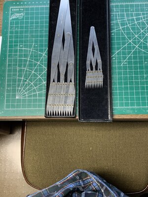
My thanks to all who have encouraged my approach to this stage of the project. I only had middle school mechanical drafting and later in architectural school a course which included perspectives for presentation renderings. Along the way I was also fortunate in being able to obtain two sizes of the 10-point dividers, the smaller 6" and a larger 12" which is useful for larger tasks. In addition I have three or four different proportional dividers, each being marked for differing uses beyond lines to circles. It would have been wonderful to have had classes in the drafting, as was early replied for body form and scantlings by @Darvis Architectvs.

My learning curve leads me into repeated attempts and revisions to obtain what seems reasonable, and I apologize for my repeated ramblings but they are true to my log and mind. My thought is that a log is a journal of documented tacks along the voyage to a home port with the finalized model at the pier.

As to construction, it is true that Egyptian's used mostly lashed securement as was found in the disassembled tomb boat by the pyramid, I have some other research papers downloaded from Academia to compare and consider. That is across the bow's horizon right now so I have plenty of time to make that decision which would still be consistent with the progression from shell to skeleton (frames) in the ancient Mediterranean. I have other papers that focus upon Egyptian construction which is not within my style of build but critical to the model by Helhmut Schrader posted in #34 above . . . precision that I cannot achieve but see as a guiding compass point. Rich (PT-2)
I forgot to attach the two 10-point dividers. Both are Theo. Altender & Sons from the early 1960s and no recalled cost for either. I mostly use the smaller 6-inch set and rarely the 12-in one.

A method of "cheating in need" (I did it in a college test one time) is to take a rubber band and mark off regular points (I used a ruler on the edge of a small slide rule). When stretched between two end points the markings will approximate the divisions. (I was spacing topographic elevation lines between given points or lines repeatedly around some ridges for a graphic drawn answer.) Graphically cast for either lines or angles any number of divisions may be made by using a straight edge and triangle but that is a bit complex to show here. I use that method regularly for dividing angles more than lines. Some of our SoS crew will likely have done that in the past also. Yes, I am a visual guy and the language of math boggles my brain while I can see visions in my headTen Point Dividers.jpg. Rich (PT-2)
 
I forgot to attach the two 10-point dividers. Both are Theo. Altender & Sons from the early 1960s and no recalled cost for either. I mostly use the smaller 6-inch set and rarely the 12-in one.

A method of "cheating in need" (I did it in a college test one time) is to take a rubber band and mark off regular points (I used a ruler on the edge of a small slide rule). When stretched between two end points the markings will approximate the divisions. (I was spacing topographic elevation lines between given points or lines repeatedly around some ridges for a graphic drawn answer.) Graphically cast for either lines or angles any number of divisions may be made by using a straight edge and triangle but that is a bit complex to show here. I use that method regularly for dividing angles more than lines. Some of our SoS crew will likely have done that in the past also. Yes, I am a visual guy and the language of math boggles my brain while I can see visions in my headView attachment 278254. Rich (PT-2)
Becoming impatient with lack of progress. . . into the garage with 34 degs inside additional new snow coming down to add to last night's deposition I proceeded to restart drawing bulkhead/frames.
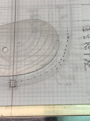
First placing dots along the hull curve previously drawn underneath:
Marking the curve with dots.jpg
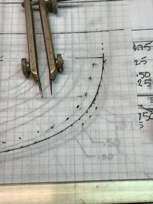
Disregard the three separate dots which were started on the wrong curve. Then using the ship's curve joining the dots for this outboard curve:
Connectking the dots with lines.jpg
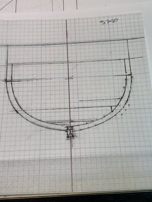
Then with small dividers mark the inside curve for the inside curve on this side of midships. Then turning the paper over and after aligning the vertical and horizontal lines, doing this process again for the other side of hell curves:
Flip it over and retrace the faint back curves.jpg
This bulkhead had the first lines on the other side show through very well. In drawing two more bulkheads with a different tracing paper which was less transparent this was not the case so I went back to the faint lines, re-dotted them and drew the curves once again for a clear set of lines on the same side.
I only could complete two more bulkheads before giving in to the frigid temperature which was slowly dropping. Disgression winning over desire I lashed the hatches down and with my watch called off I headed inside for warmer temps and a hot "mug-up". Cheers!!! Rich
 
Becoming impatient with lack of progress. . . into the garage with 34 degs inside additional new snow coming down to add to last night's deposition I proceeded to restart drawing bulkhead/frames.
First placing dots along the hull curve previously drawn underneath:
View attachment 278294
Disregard the three separate dots which were started on the wrong curve. Then using the ship's curve joining the dots for this outboard curve:
View attachment 278295
Then with small dividers mark the inside curve for the inside curve on this side of midships. Then turning the paper over and after aligning the vertical and horizontal lines, doing this process again for the other side of hell curves:
View attachment 278296
This bulkhead had the first lines on the other side show through very well. In drawing two more bulkheads with a different tracing paper which was less transparent this was not the case so I went back to the faint lines, re-dotted them and drew the curves once again for a clear set of lines on the same side.
I only could complete two more bulkheads before giving in to the frigid temperature which was slowly dropping. Disgression winning over desire I lashed the hatches down and with my watch called off I headed inside for warmer temps and a hot "mug-up". Cheers!!! Rich
As can be seen above, I did not previously comment upon correcting the lower left curve at the keel to correspond to the opposite end point. This shows up well in the close photo which my poor vision did not see until I was in the retracing phase. My curves do not precisely match the dots but I will cut the bulkheads sufficiently outboard to bring them to true fared faces when all are in place and test wales applied for full hull faring. I don't know if it is the cold temp. or just old ink in these pens which causes the poor line quality. I may need to go and buy some new pens than these 15 years mature set. Rich
 
As can be seen above, I did not previously comment upon correcting the lower left curve at the keel to correspond to the opposite end point. This shows up well in the close photo which my poor vision did not see until I was in the retracing phase. My curves do not precisely match the dots but I will cut the bulkheads sufficiently outboard to bring them to true fared faces when all are in place and test wales applied for full hull faring. I don't know if it is the cold temp. or just old ink in these pens which causes the poor line quality. I may need to go and buy some new pens than these 15 years mature set. Rich
Draftsmen use mechanical pencils, not ink. 0.5mm for standard dark lines, 0.7mm for heavy lines, and 0.3mm for light thin lines. Get a BIG old fashioned parallelogram shaped eraser (you're gonna need it) and French or ship curves. These tools make the job a lot less messy and a lot easier. I also had a long flexible, adjustable curve, which is useful for drawing the sweeping curves of wales, etc. I lost most of my old draftsman tools years ago, including my drafting table, and really wish I still had them. Back in the day, it was good practice to make light lines while drafting a blueprint, then go over the lines a second time with the correct thickness and make them fully dark.

Good tools are where you find them: LINK
 
Last edited:
Draftsman use mechanical pencils, not ink. 0.5mm for standard dark lines, 0.7mm for heavy lines, and 0.3mm for light thin lines. Get a BIG old fashioned parallelogram shaped eraser (you're gonna need it) and French or ship curves. These tools make the job a lot less messy and a lot easier. I also had a long flexible, adjustable curve, which is useful for drawing the sweeping curves of wales, etc. I lost most of my old draftsman tools years ago, including my drafting table, and really wish I still had them. Back in the day, it was good practice to make light lines while drafting a blueprint, then go over the lines a second time with the correct thickness and make them fully dark.

Good tools are where you find them: LINK

I am not familiar with using pencils for the final lines, we were only allowed to use pencil to setup and draw the initial points and lines, but the final curves had to be in ink. Pencil was to easily erased or degraded too much over time, making longevity an issue, hence the inking requirement. I think the requirement came about after unfavorable experiences with an early post WW2 practice of pencil drawn views, and notes and dimensions in ink
Once I started in the draftsman's world, full scale drawings were to be drawn with 0,25mm ink pens with an accuracy of +/-0,2mm. For scaled drawings we were to use thicknesses as indicated by Kurt.
French curves are nice, but have limited practical use, other than for areas with tight curves. Kurt's practice of using long, thin and flexible curves, temporarily fixed with weights, always gave me the best results for 80-90% of the curves to be drawn. Even for relatively short curves (frame cross sections) I would rather use the flexible curve, especially when connecting points.
As far as Rich work goes, whatever method yields the required results is game...
I agree with all of this. My pens are pretty well dried out so I am having to use a roller ball gel type of the smallest that I have. I also had a K&E flexible curve long ago but it disappeared along the way. I saw a short 12 inch one on line for about $50 as I recall and the same type in 24 " had been sold. The current flexible rubber rods are a joke in my mind. The type that you describe with the fixation pins and wieghts show up in photos of drawing large, 1:10 or maybe full size lines on long tables/media. I don't expect these lines to do anything more than get copied and laid down on a thin plank for cutout and refining filing. My curves were not intended for ships curves, only architectural drafting where needed, but they provide a close match for the current offsets. Again for the small model, final filing and sanding will be necessary for smooth lines.
Rich
I used to use Kohinoor Rapidograph pens with India ink. They needed to be cleaned often. I used an ultrasonic cleaner. But went to AutoCAD back at 1.0. Still have a large format printer.
 
I used to use Kohinoor Rapidograph pens with India ink. They needed to be cleaned often. I used an ultrasonic cleaner. But went to AutoCAD back at 1.0. Still have a large format printer.
We used Rotring pens. A disaster to clean, especially if they weren't used for a while. CADAM and later CATIA were a gigantic leap forward.
 
Somewhere I have an old box with compass and pencils and all that came in small graphic drafts kit.

In one of my jobs in the Air Force we had to support offices with training slides. Mostly copies of documents turned into 34mm slides.

Sometimes we had to make fixes for them and I had a kit given to me by our graphic chief.
 
I agree with all of this. My pens are pretty well dried out so I am having to use a roller ball gel type of the smallest that I have. I also had a K&E flexible curve long ago but it disappeared along the way. I saw a short 12 inch one on line for about $50 as I recall and the same type in 24 " had been sold. The current flexible rubber rods are a joke in my mind. The type that you describe with the fixation pins and wieghts show up in photos of drawing large, 1:10 or maybe full size lines on long tables/media. I don't expect these lines to do anything more than get copied and laid down on a thin plank for cutout and refining filing. My curves were not intended for ships curves, only architectural drafting where needed, but they provide a close match for the current offsets. Again for the small model, final filing and sanding will be necessary for smooth lines.
Rich
Rich, there is nothing wrong with your ‘old fashion’ approach. A basic drawing as a indication and further adjusting by filing and sanding. I do use it also by my BN. And sometimes some help with Photoshop on the Mac. Because a have no 10-points divider. :)
We used Rotring pens. A disaster to clean, especially if they weren't used for a while. CADAM and later CATIA were a gigantic leap forward.
I still used the Rotring's last year. :) For the white window frames on the sheets for the windows of my Lee. After use, do indeed clean it.
Regards, Peter
 
Rich, there is nothing wrong with your ‘old fashion’ approach. A basic drawing as a indication and further adjusting by filing and sanding. I do use it also by my BN. And sometimes some help with Photoshop on the Mac. Because a have no 10-points divider. :)

I still used the Rotring's last year. :) For the white window frames on the sheets for the windows of my Lee. After use, do indeed clean it.
Regards, Peter
Tacking over from the drafting tack and back to historical research findings related not only to my present boat but of those AD and possible lanteen sails and rigging are the small devices for temporary securing of lines - Toggles:
I have not been successful in copying the direct PDF research paper link so I will put the title up on this pier for a hunt and find by interested crew members:
"Toggles and Sails in the Ancient World: Rigging Elements Recovered from the Tantura B Shipwreck, Istael:

This link???? may work: https://onlinelibrary.wiley.com/doi/abs/10.1111/j.1095-9270.2008.00188.x
Or try this: https://www.bing.com/search?q=Toggl...-57&sk=&cvid=A018003923254A06B5132500E76A232B

Several wrecks in the lagoon were found and this one from the Ninth C AD was investigated in particular and is the source of much of the paper's findings and conclusions. which I found interesting and of possible inclusion in larger models.
Sorry about the bad linkage attempts. Rich
 
Tacking over from the drafting tack and back to historical research findings related not only to my present boat but of those AD and possible lanteen sails and rigging are the small devices for temporary securing of lines - Toggles:
I have not been successful in copying the direct PDF research paper link so I will put the title up on this pier for a hunt and find by interested crew members:
"Toggles and Sails in the Ancient World: Rigging Elements Recovered from the Tantura B Shipwreck, Istael:

This link???? may work: https://onlinelibrary.wiley.com/doi/abs/10.1111/j.1095-9270.2008.00188.x
Or try this: https://www.bing.com/search?q=Toggles and Sails in the Ancient World: Rigging Elements Recovered from the Tantura B Shipwreck, Israel&qs=n&form=QBRE&sp=-1&pq=toggles and sails in the ancient world: rigging elements &sc=0-57&sk=&cvid=A018003923254A06B5132500E76A232B

Several wrecks in the lagoon were found and this one from the Ninth C AD was investigated in particular and is the source of much of the paper's findings and conclusions. which I found interesting and of possible inclusion in larger models.
Sorry about the bad linkage attempts. Rich
The Second Link does bring the paper up with the colored photos and drawings but I didn't see a download button there. Maybe the dusk and my poor eyes missed the button for that but at least there is a visual read-through possible.
Rich
 
The Second Link does bring the paper up with the colored photos and drawings but I didn't see a download button there. Maybe the dusk and my poor eyes missed the button for that but at least there is a visual read-through possible.
Rich
With recent sub-freezing temps my drafting surface has shrunk and the ink, what there was has vanished. Pens/ink problem being solved by exchanging some cash for new technical pens. No drawing feasible until temperatures go back up and the plastic drafting surface on the table expands again. It is only secured along the top edge so most expansion is vertically with movement on the bottom edge but there is lateral movement as well that needs to settle down. The expansion rate is different between the plastic and paper so the present waves on the paper will have to flatten out and checked again for true alignment of the drawings. Time out to practice on my Irish Tin Whistle and Concertina. Maybe I can restore some lost flexibility to my fingers. Rich
 
With recent sub-freezing temps my drafting surface has shrunk and the ink, what there was has vanished. Pens/ink problem being solved by exchanging some cash for new technical pens. No drawing feasible until temperatures go back up and the plastic drafting surface on the table expands again. It is only secured along the top edge so most expansion is vertically with movement on the bottom edge but there is lateral movement as well that needs to settle down. The expansion rate is different between the plastic and paper so the present waves on the paper will have to flatten out and checked again for true alignment of the drawings. Time out to practice on my Irish Tin Whistle and Concertina. Maybe I can restore some lost flexibility to my fingers. Rich
My drafting table had a Borco cover on it. Was inside - never outside in the cold....
 
My drafting table had a Borco cover on it. Was inside - never outside in the cold....
Inside, as in an office, is where these covers were intended to be used by the person or their employer! I ran out of room long ago when I retired with too much furniture and archived drawings for a good replacement drafting area. I gradually got rid of some of most of those but kept the 3'x5' drafting table with the 48" parallel ruler and the large flat drawer beneath from the closed office delegated to the garage, displacing my former Jeep and relegating my Outback in the driveway outside. Such is life! Rich
 
Inside, as in an office, is where these covers were intended to be used by the person or their employer! I ran out of room long ago when I retired with too much furniture and archived drawings for a good replacement drafting area. I gradually got rid of some of most of those but kept the 3'x5' drafting table with the 48" parallel ruler and the large flat drawer beneath from the closed office delegated to the garage, displacing my former Jeep and relegating my Outback in the driveway outside. Such is life! Rich
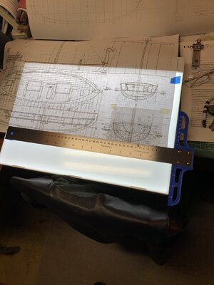
The illuminated tracing box arrived, so now with a new set of technical pens and a small T-square, I can restart drawing the mold bulkheads in the comfort of my den/hobby room, and more able to assist my wife in her needs without calling me on the cell phone to come in from the garage. Rich
Tracing LIght Box.jpg
 
Back
Top