Yes I've done that. Your helpfulness is an outstanding feature of your company.Hi Van. You can always Email: ModelshipDockyard@gmail.com or PM me if you need any help. Hope you enjoy the build.
-

Win a Free Custom Engraved Brass Coin!!!
As a way to introduce our brass coins to the community, we will raffle off a free coin during the month of August. Follow link ABOVE for instructions for entering.
-

PRE-ORDER SHIPS IN SCALE TODAY!
The beloved Ships in Scale Magazine is back and charting a new course for 2026!
Discover new skills, new techniques, and new inspirations in every issue.
NOTE THAT OUR FIRST ISSUE WILL BE JAN/FEB 2026
You are using an out of date browser. It may not display this or other websites correctly.
You should upgrade or use an alternative browser.
You should upgrade or use an alternative browser.
Another Hayling 1760 build
- Thread starter Tom of all trades
- Start date
- Watchers 29
- Joined
- May 31, 2021
- Messages
- 86
- Points
- 88

Hihello
am starting the rigging and am at a lost understand the main mast. info is not very informative so if you have any more info or photos of the main mast would be much appreciated,
Jean-Bernard Mallet
I didn't build the model any further than the last photo. I suggest you check out the other Hayling builds on this forum to see how they got on.

- Joined
- Mar 1, 2022
- Messages
- 683
- Points
- 308

Dear Mr Mallet, I'm currently building that very model. I own a copy of Antscherl monograph as well, so I might be able to help you up with your specific issue. Please, feel fre to PM me, if you will. Cheers. Albertohello
am starting the rigging and am at a lost understand the main mast. info is not very informative so if you have any more info or photos of the main mast would be much appreciated,
Jean-Bernard Mallet
hello Alberto
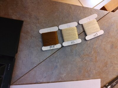
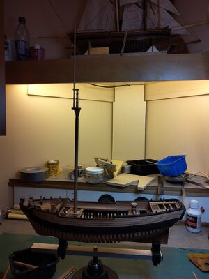
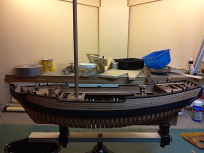
here is a few photo's of my build , am at the rigging stage and the size of the tread are a problem in my kit i have 3 spool with numbers ( photo) . from pass experience i always had to get extra rope .
hope that will not be the case for this one ,
rudder hinges supply for the kit are not the proper size for the wood rudder had to use part from other model , did you experience the same problem


Hallo @Tom of all tradesAs requested by Jim, here's my build log of the Model Dockyard POF Hayling 1760 (I will try my best to keep it updated... honest).
First off, the quality of the kit contents is excellent - and I really mean that. The wood and etched sheets are the best I've ever seen. I've never used pear wood before so it's a new experience for me and found it to be very close grained, a wonderful colour but a bit hard unlike good old bass wood which is really easy to carve.
But...
The instructions are very minimal and the 3D renderings sometimes don't match the model which means you have to do some head scratching to work out what should be happening. All in all, though, a good value kit.
So to my build...... First off the center frames on the jig:
The bow frames are next... you can see the frames with the extensions which are not shown in the drawings...
This is where it gets interesting.. the slots are labelled F1 to F4 but the instructions say there is an F5 but the jig markings don't have an F5 slot although it look like there should be a gap between F4 and F5... most confusing...
And when F4 is slotted in, there appears to be no space for F5 pieces...
As the drawings show F4 and F5 as being one piece so I've decided to glue both F5 parts to F4 and carve the complete assembly to fit the gap. Which I think is what the instructions meant.
Wish me luck. I'll update when (if) I manage to get it to look right.
Cheers
we wish you all the BEST and a HAPPY BIRTHDAY


