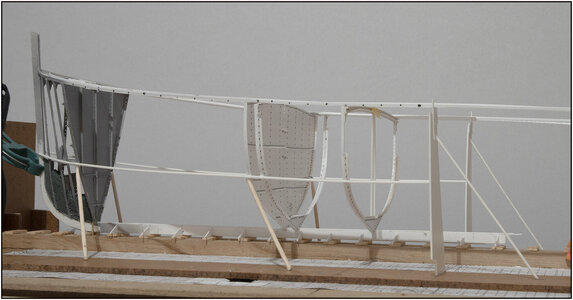
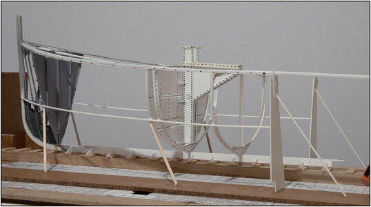
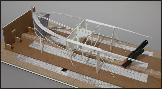
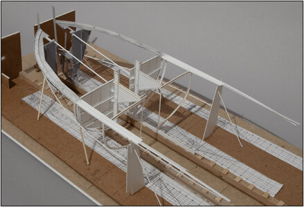
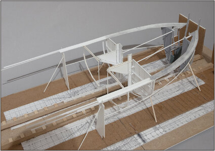
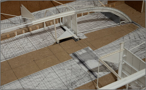
Then it is now frame 33's turn. The point / rear of the kossing rests on the deck beam of this frame.
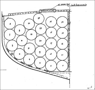
Here too I had to think one step ahead. Frame 33 is part of the cargo hold for the herring barrels. A transverse bulkhead is placed on the frames every second frames. It makes it easy that it is always the frames with an odd number. The distance between these odd frames is derived from the height of the barrels. The barrels are stacked on their sides between the bulkheads:
View attachment 416752
The barrels then rest against the frame placed between the two 'odd' frames. This has a retaining frame up to the deck and then also serves as a weighing. The drawing does show some weighing planks. I'll see later how that looks in the model.
Each room has its own hatch on the deck, which is also tailored to the size of the barrels.
I mentioned earlier that every frame with a deck beam has a retaining frame up to the height of the bilge. A U-profile is placed on the retaining frame in which the transverse bulkhead is placed. A U-profile has also been installed along the deck beam. The planks that form the bulkhead are then slid into those U-profiles.
But a photo makes more clear than a piece of text. I took photos of different steps of making the frame and shows all the parts.
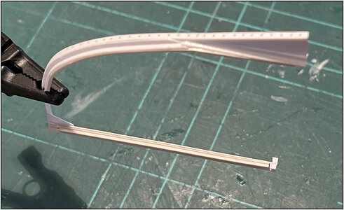
Before bending the curve, I first warm the strip a bit. I first did that on the side of a kettle. But I still have an old-fashioned halogen lamp hanging above my work table. It also provides a lot of warmth. I now move the strip along that and start bending:
View attachment 416753
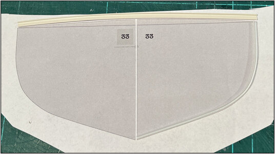
I use the print of the frame and bend along the lines. Here the formation of the retaining frame. I first bend the strip a little beyond the curve and then feed it back to the stripe of the print.
The same with the deck beam:
View attachment 416754
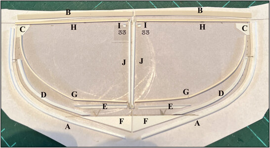
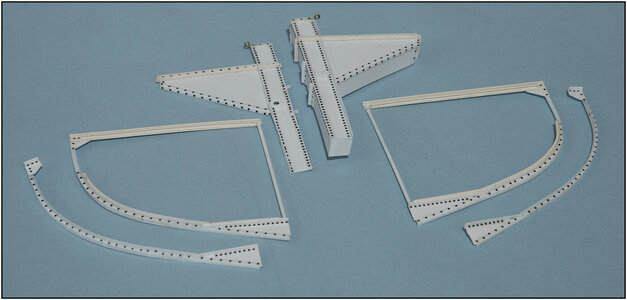
After some bending, all parts were made:
View attachment 416755
A: the hull profile
B: the deck beam
C: the knee
D: the hull retaining frame up to and including the bilge rounding
E: the floor profile of the retaining frame
F: the wrang (deep floor plate?) between the hull profile and the floor retaining frame part
G: U-profile for on the retaining frame
H: U-profile for against the deck beam
I: knee where the longitudinal L-profile will later be placed over the center of the deck
J: cargo hold strut
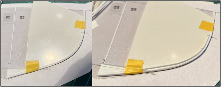
I first glued the wrang in the bottom corner of the hull profile and on top of that the floor part of the retaining frame:
View attachment 416756
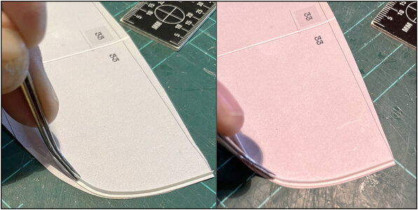
I then secured this part with tape to a template that I made with the print of the frame. (Photo left) To ensure the shape.
I glued the other part of the retaining frame there. (Photo right)
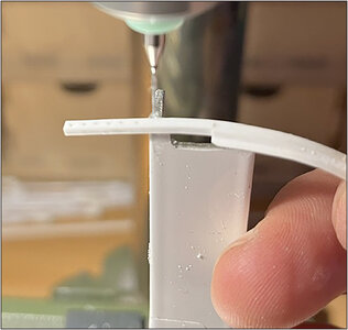
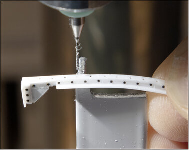
Now I could provide the holes for the rivets in this part, which goes into the open starboard side:
View attachment 416757
I couldn't do that before because then the profile would buckle at the holes when bending. (Next time focus on the right spot

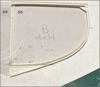
Then all parts combined:
View attachment 416758
Place the parts on the print at each step to always check the shape and roundness.
I can only install the struts later when the deck longitudinal profile and the keelson with corner profile are installed.
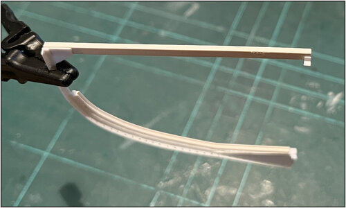
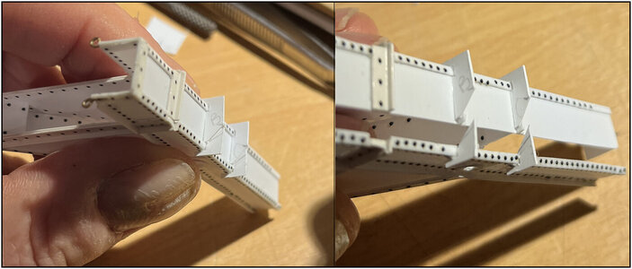
The whole with a view of the underside with retaining frame and U-profile:
View attachment 416759
And vice versa with the U-profile along the deck beam:
View attachment 416760
Regards, Peter


