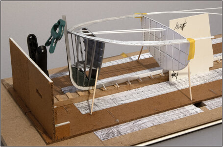
My intention was to now build the 2nd compartment: the forecastle between bulkheads 51 and 39.
After studying the old drawings, I came to the conclusion that I would be getting myself into trouble.
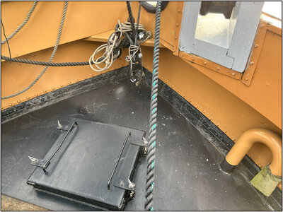
30 cm behind bulkhead 39 is the mast tube that is also connected to bulkhead 39. And the 'kossing' is also located on the mast tube. This is a triangular box in which the mast approximately 45 dgr can be tilted backwards.
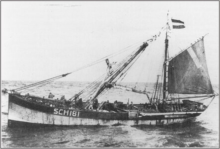
(Source: Scheepvaartmuseum Restoration Book, page 27, photo from the Vlaardingen Visserijmuseum collection)
This was done when the ship was 'aan de vleet'. The foremast then picked up less wind, making the ship more stable with only the mizzen sail behind the fishing nets and not pulling on it too hard.
The mast is tilted at an angle of 2 degrees, so that the mast tilts just along the mizzen mast. The mast is therefore not on the keel beam but hinges on a pin at the bottom of the cossing, in the tube.
The tube and kossing are in the middle of the deck. Cutting this in half, just like the hatch on the forepeak, causes even more problems. What do I do with the mast?
The mast tube and kossing will therefore be located in the port side, which will be fully equipped. This means that it will partly protrude beyond the center line. In order to be able to tilt my construction jigs to align the half frames on the flat base plate, I have to make a hole in the base plate, where the mast tube and kossing have fallen. Then I need to know their correct position and how best to cut the bulkhead 39.
So first build that 39 and that tube with kossing. Then I can hold it in any position on my work table for alignment.
The advantage is that after installation, the two will also provide more strength in the longitudinal direction.
The bow section with frames 51 to 54 is now only attached to the keel and under the stringers. With the small floor. That gives some unwanted flexibility in the longitudinal direction.
I added part of the old construction drawing in Photoshop into the drawing of the line plan:
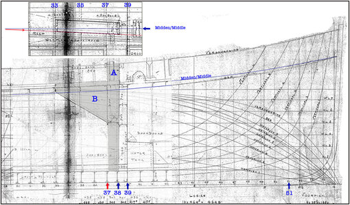
A: the mast tube.
B: the 'Kossing'.
At the bottom are the numbers of the frames that are important.
In both drawings I have to keep a close eye on the fact that the deck line on the line plan is the outside of the deck and that on the construction drawing the deck line in the middle of the deck is also decisive.
I have inserted a cutout of the top view at the top left.
It shows that the mast and the front of the hole of the kossing are drawn slightly in the shape of a parallelogram. The front and rear of the mast and cossing run parallel to the deck beams. The sloping sides then left and right.
If the mast were to tilt backwards, the sloping sides would tilt and rotate up and down. That's going to be a problem. Or the mast tube must be wider than the mast base. But then the mast tube loses its effectiveness. It can be seen on the Balder itself and in the restoration specifications that the mast base is square.
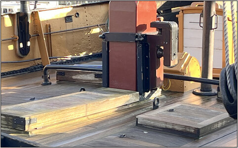
Also with a rectangular hood as a cover over the opening of the kossing. This point clearly deviated from the specifications drawing.
The old specifications state:
"The mast tube and cossing are composed of sheet material and angle irons. The rear is open. It took some searching and puzzling on the drawings to see what the construction was like.
But this photo also helped:
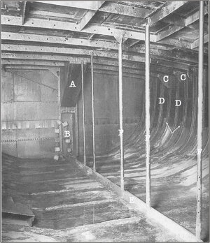
(Source: Maritime Museum Restoration Book, page 68)
A: Kossing.
B: open side of the mast tube.
C: Knees on the frames with deck beams with retaining frames up to the bilge.
D: The frames without deck beam with retaining frames up to the deck.
E: The keelson
F: Sticks placed on the sawn keelson to support the deck.
Made 2 prints and glued them to the right place on the base plate:
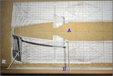
Then I can use the tilted construction template B to determine the correct position on the base plate A.
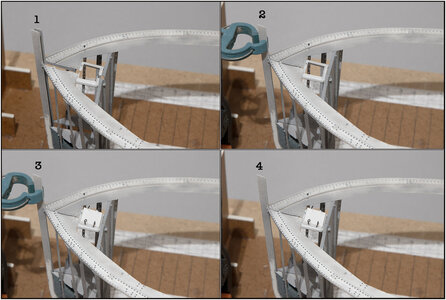
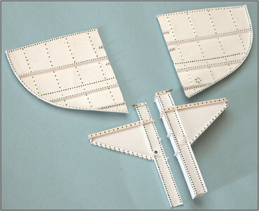
Started making watertight bulkhead 39 and the mast tube with kossing:
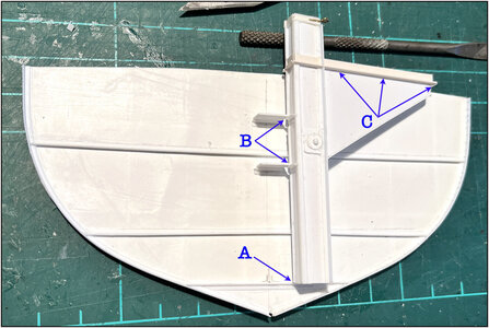
Easy to handle, I was now able to determine 3 important positions correctly:
A: the foot that rests on a plate that comes between the horizontal profiles of the retaining frames 37 and 39.
B: the plates that form the connection between the profile pieces on 39.
C: the profile that will later rest on the deck beam pieces of frames 33, 35 and 37. So I am going to position those deck beams under that profile.
In order to provide longitudinal strength in the open starboard part, the side plate was left loose:

A: the port side.
B: the starboard plate.
With the axle on the inside on which the mast base can later be tilted:
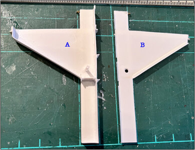
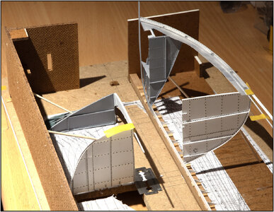
The dry-fit to see if everything is correct:
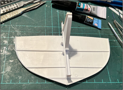
and what it looks like in position:
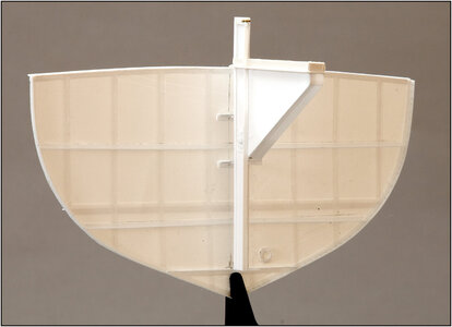
Now make a hole in the base plate for further alignment and a piece of plate where the angle is set to 88 degrees. To align the kossing at the 2 degrees.
Regards, Peter


