BALDER, Vlaardingen Herring Lugger from 1912, scratch build scale 1:50 Plate-On-Frame

Peter this has to be a most satisfying process for you. From CAD to fabrication of parts to actual construction seems to work well!
The detail you achieve with items like rivets are remarkably well done.
Thanks for the compliments m, Daniel. I see it as a big adventure where I have no travel documentation. There is a lot to think about and work out. But so far the results are indeed satisfactory.
Regards, Peter
 
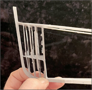
The next step was to place the 4 frames on the starboard part of the keel. These had to be on the same line as the 4 on the port side.
But if you use the same drawing for both, with one mirrored, and use the same drawing in Fushion for the frames, then you can't really go wrong.
That also turned out... with this result:
0126 2x4.jpg
0127 2x4.jpg
But I cannot photograph the parts neatly on the tilting construction templates.

Spraying the parts does not work well if the parts are on the construction molds. Also including the beam wedges that are stuck to the keel to keep them in position.
I was also already thinking about how I wanted to set up both parts: as loose as possible with some bracing.
Therefore, both parts were detached from the keel beam. Just a matter of loosening all the beam wedges.

I glued small pieces of brass pipe, internally 1 mm, to the bottom front of both half-watertight bulkheads 51.
0128 Buis.jpg
I placed a piece of 1 mm brass rod in the correct position on the keel beam of both parts. A matter of measuring carefully.
Now I can place both parts back on the keel beam, almost free-standing, and continue building. Just gluing a few beam wedges to the keel again. I always do this with some wood glue so that the wedges stick, but the wood glue does not penetrate the Evergreen.

I immediately made 2 planks for taking photos.
Because both parts are now loose, I could also easily paint them.
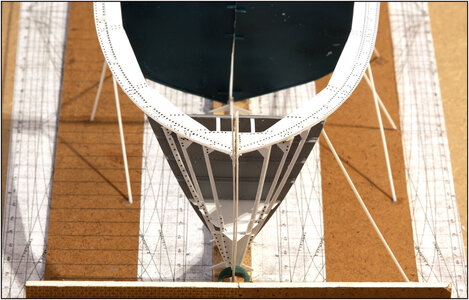
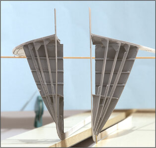
The front with both parts against each other:
0129 Dubbel.jpg
It is still quite a precarious balance between just these 4 frames. With the next compartment behind it there will be more strength.

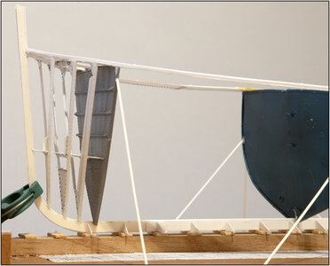
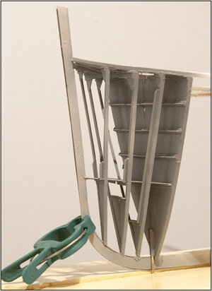
Slanting from the side:
0130 Dubbel.jpg
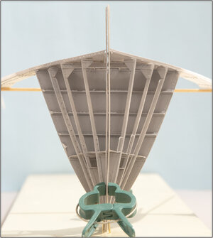
A little clamp helps to hold both parts together.

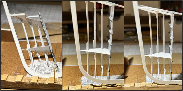
And slightly apart:
0131 Dubbel.jpg
For safety, these planks will also have braces. Because on 1 brass rod of 1 mm....... that's asking for problems.

I now have a solution on 3 chapters. As far as I am concerned, my tests have been successful and the question of 'go or no go' is clear: further construction must be successful. So a GO.
There are still a lot of questions on my list to solve. But they will see that during further construction.
Regards, Peter
 
Last edited:
Looks good Peter. Scratch building a hull without the use of a hull jig is exciting to watch!
Thanks, Daniel.
In addition to what I wrote to Johan, everything must have the correct shape in advance with a check on the drawings, a check on the other parts from all 4 sides, with always a dry-fit.
Just a photo with reference for your idea of the size:
0132 Reference.jpg
Regards, Peter
 
The next step was to place the 4 frames on the starboard part of the keel. These had to be on the same line as the 4 on the port side.
But if you use the same drawing for both, with one mirrored, and use the same drawing in Fushion for the frames, then you can't really go wrong.
That also turned out... with this result:
View attachment 408636
View attachment 408637
But I cannot photograph the parts neatly on the tilting construction templates.

Spraying the parts does not work well if the parts are on the construction molds. Also including the beam wedges that are stuck to the keel to keep them in position.
I was also already thinking about how I wanted to set up both parts: as loose as possible with some bracing.
Therefore, both parts were detached from the keel beam. Just a matter of loosening all the beam wedges.

I glued small pieces of brass pipe, internally 1 mm, to the bottom front of both half-watertight bulkheads 51.
View attachment 408638
I placed a piece of 1 mm brass rod in the correct position on the keel beam of both parts. A matter of measuring carefully.
Now I can place both parts back on the keel beam, almost free-standing, and continue building. Just gluing a few beam wedges to the keel again. I always do this with some wood glue so that the wedges stick, but the wood glue does not penetrate the Evergreen.

I immediately made 2 planks for taking photos.
Because both parts are now loose, I could also easily paint them.
The front with both parts against each other:
View attachment 408639
It is still quite a precarious balance between just these 4 frames. With the next compartment behind it there will be more strength.

Slanting from the side:
View attachment 408640
A little clamp helps to hold both parts together.

And slightly apart:
View attachment 408641
For safety, these planks will also have braces. Because on 1 brass rod of 1 mm....... that's asking for problems.

I now have a solution on 3 chapters. As far as I am concerned, my tests have been successful and the question of 'go or no go' is clear: further construction must be successful. So a GO.
There are still a lot of questions on my list to solve. But they will see that during further construction.
Regards, Peter
Good morning Peter. I am blown away, and then you show how small this is……you have exceptional skills. Cheers Grant
 
nah... you have oversized fingers! ;)
Yeh, to build it with those big fingers …… and small tweezers…….
Good morning Peter. I am blown away, and then you show how small this is……you have exceptional skills. Cheers Grant
Thanks, Grant.
But I also had doubts, headaches, sweat on the brow, sometimes a big ggggrrrrrr and points for improvement.
On to the 2nd compartment: the forecastle.
Regards, Peter
 
In order not to make 54 frames one after the other, as with my Bluenose, I now intend to finish this model on the inside per compartment.
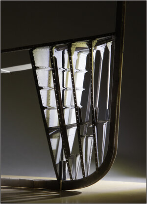
This must also be done on the starboard side. They have already drilled all the holes on the shipyard on the side of the frames for the rivets with which the skin plates would be secured:
0133 Drilled.jpg
I could immediately play with the light. The starboard side therefore remains open and continues to provide a view of the internal structure of all profiles.

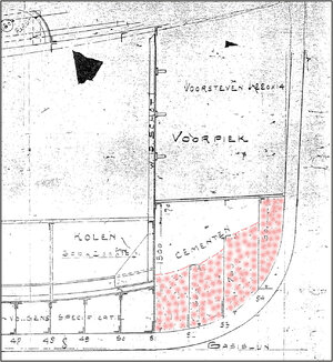
On the port side, the lower part of the bow is provided with cement:
0134 cement.jpg
The cement part is accentuated with some dots. I read in the old fittings that they also called the watertight bulkhead 51 the collision bulkhead. Then the cement also helps to prevent major deformations.

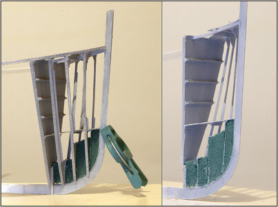
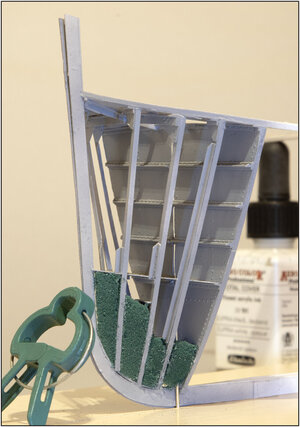
A member of the Dutch forum had already drawn my attention to (gray) floral foam. Bought some blocks today and started playing around a bit:
0135 cement.jpg
Visible here through the frames in the port side. Only there is virtually no adhesive to that stuff......... grrrrr. I let some glue for gluing Evergreen flow between. But a little too much and it makes the Evergreen soft.

What it looks like on the outside:
0136 cement.jpg
Here it does not have to be finished very neatly, because there are skin plates anyway. So only visible on the open side.
By the next round of painting, I will give it a nice color.
Regards, Peter
 
Last edited:
Back
Top