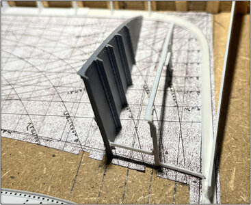
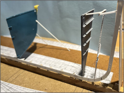
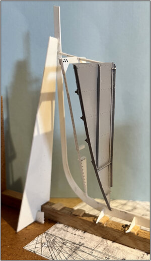
Time to post again. Over the past week I've been thinking and puzzling a lot about how to build. Because theory and practice do not yet go together.
I think my intended method for installing the frames will not work:
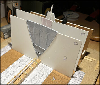
I intended to place the half frame templates B on the construction template A, which I obtain when I have cut out the shape of the frame in question.
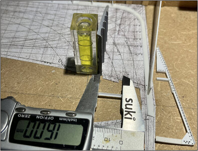
Here I placed 51 and 53. 52 and 54 still have to be added here in-between. On average, a frame of 1.5 mm every 9 mm.
(Depending on the amount of shaving light, the small rivets show quite nicely.)
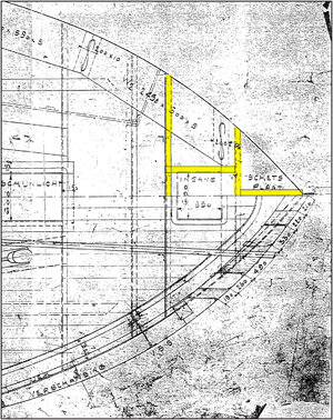
To align the frame jigs I also wanted to use a template that has the shape of the deck:
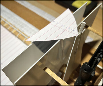
On which I drew the frames.
The construction templates are placed so close together that I have virtually no space left to properly align the frames to be installed and to provide them with the necessary longitudinal profiles.
And I need to start connecting all the frame templates together to take up all the slack.
I thought about it for a while again and now I'm going to do it without the frame templates, as a 2nd test.
Therefore, first made frame 53:
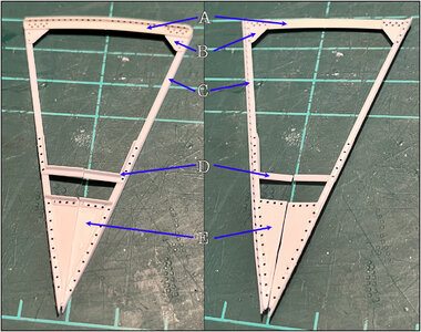
A: deck beam
B: knee
C: frame
D: retaining frame (keerspant)* that carries the floor plate in the forepeak (forgotten the rivets at the bottom......)
E: vrang/wrang - flange or deep floor? I don't know the exact English name of those plates.
All connections provided with rivets.
*A small addition to the retaining frame that is partly attached to the frame.
The old specifications state:
"Retaining frames on each frame, every other frame up to deck or top of bilge".
Yesterday I went to see the Balder in Vlaardingen again. And partly based on photos during the restoration, it appears:
-frames with a deck beam, the retaining frame extends to the bilge.
-frames without a deck beam, the retaining frame extends to the deck. There it has a small knee and the top of that knee is attached to the stringer with a small piece of profile, a 'little man'.
And on the Balder it became visible that the frames and retaining frames are stacked together in such a way that they form a perpendicular Z.
-In the front part of the ship, the upper part of the deck L-profile points forward. These point backwards from the watertight bulkhead 39.
These are small details, but they do determine the direction of the frames and the retaining frames.
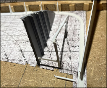
In the frame 51 in the photo above you can see that behind the downward-facing part of the deck beam is the knee and behind the knee is the frame. The retaining frame is then again on the side of the deck beam.
This is also a confirmation of how I had read the old drawings. The invisible profile parts are drawn with a dotted line.
Back to my 2nd test for installing the frames.
To keep the half frames in position I will connect them to the stringers on the outside:
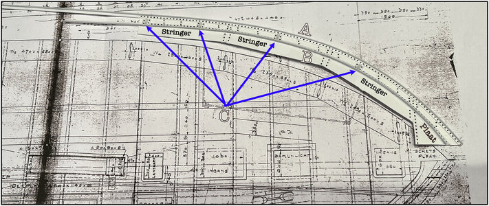
A: L-profile on the outside of the deck
B: L-profile that faces inwards and against which the wood of the deck rests
C: the pieces of profile (little man) between which the bulwark plates will later be placed.
I will now install these 2 frames with the stringer on the outside and a few other pieces of profile as a mutual connection between the frames. Then the frames 52 and 54.
This will also be a test to see whether I still have enough space to spray paint all parts in color per compartment.
Please be patient, but I will try to take some pictures of all the steps in between.
Regards, Peter


