-

Win a Free Custom Engraved Brass Coin!!!
As a way to introduce our brass coins to the community, we will raffle off a free coin during the month of August. Follow link ABOVE for instructions for entering.
-

PRE-ORDER SHIPS IN SCALE TODAY!
The beloved Ships in Scale Magazine is back and charting a new course for 2026!
Discover new skills, new techniques, and new inspirations in every issue.
NOTE THAT OUR FIRST ISSUE WILL BE JAN/FEB 2026
You are using an out of date browser. It may not display this or other websites correctly.
You should upgrade or use an alternative browser.
You should upgrade or use an alternative browser.
BALDER, Vlaardingen Herring Lugger from 1912, scratch build scale 1:50 Plate-On-Frame
- Thread starter Peter Voogt
- Start date
- Watchers 65
- Joined
- Sep 3, 2021
- Messages
- 5,197
- Points
- 738

PS A drawing error is also possible: we once found a 10 mm deviation for a wing attachment point in the master tooling. Luckily everything else was derived from said master tooling. We only discovered this discrepancy when we modeled the entire geometry in 3D and compared it with the master tooling models.You're absolutely right taking the line plan as your starting point, no questions asked.
With respect to the observed difference of 50mm; it appears that the 1550mm dimension is taken from the intersection of WL6 and (imaginery) frame 55, or your origin, to frame datum 51. The 1500 dimension seems to be taken from the intersection of the inner profile of the bow and the floor of the focsle to frame station 51. Unfortunately the construction drawing is not very clear, but it may be a plausible explanation.
View attachment 402971
Thanks for diving with me into de details of the drawings, Johan.You're absolutely right taking the line plan as your starting point, no questions asked.
With respect to the observed difference of 50mm; it appears that the 1550mm dimension is taken from the intersection of WL6 and (imaginery) frame 55, or your origin, to frame datum 51. The 1500 dimension seems to be taken from the intersection of the inner profile of the bow and the floor of the focsle to frame station 51. Unfortunately the construction drawing is not very clear, but it may be a plausible explanation.
View attachment 402971
The distance between those 4 is also different: 4x387.5 and 380/390/390/330.
This is not only the case here, but also with other frames. The differences are not large, but 'several times a little bit' gives undesirable differences. Especially because I have aligned everything with the sheer and curve on the outside of the deck via the lines plan.
Regards, Peter
Always: check, check, double check ……..PS A drawing error is also possible: we once found a 10 mm deviation for a wing attachment point in the master tooling. Luckily everything else was derived from said master tooling. We only discovered this discrepancy when we modeled the entire geometry in 3D and compared it with the master tooling models.
- Joined
- Sep 22, 2023
- Messages
- 238
- Points
- 213

Quando i risultati superano le aspettative la soddisfazione è maggiore.Thanks, Alessandro. I am also happy with the result. Hoped in advance, but certainly not expected.
Regards, Peter
When results exceed expectations, satisfaction is greater.
- Joined
- Sep 3, 2021
- Messages
- 5,197
- Points
- 738

I again looked at the details you provided and I think the pitches are 390/390/390/330(=1500) and not 380/390/390/330(=1490).Thanks for diving with me into de details of the drawings, Johan.
The distance between those 4 is also different: 4x387.5 and 380/390/390/330.
This is not only the case here, but also with other frames. The differences are not large, but 'several times a little bit' gives undesirable differences. Especially because I have aligned everything with the sheer and curve on the outside of the deck via the lines plan.
Regards, Peter
That 2,5mm difference is a bit strange (the outlayer 330 not taken into account), which I can't really explain.
When you state that you observe similar deviations on other frames, you might be onto something; one error is possible, a second, similar error becomes a bit suspicious, but a third and consecutive deviations are no errors any more, that's deliberate. It might be a good idea to look for a rationale behind the deviations you find. Or stick to your plan and declare your basic surface and plane definitions being the "Bible".
Hi Johan. You are correct about the "380". The accent line went through the digits and its 390. Then the outcome is 1500.I again looked at the details you provided and I think the pitches are 390/390/390/330(=1500) and not 380/390/390/330(=1490).
That 2,5mm difference is a bit strange (the outlayer 330 not taken into account), which I can't really explain.
When you state that you observe similar deviations on other frames, you might be onto something; one error is possible, a second, similar error becomes a bit suspicious, but a third and consecutive deviations are no errors any more, that's deliberate. It might be a good idea to look for a rationale behind the deviations you find. Or stick to your plan and declare your basic surface and plane definitions being the "Bible".
About the other deviation: not as a error but the position of some frames also differs elsewhere. An example:
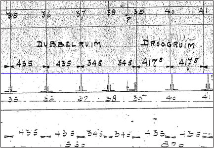
Above the blue line, a part of the Line plan. Below a part of the Construction plan. Both in the same resolution and scale.
Between 35 to 39 the same values but the next 2 are different.
On another old bad cross-section drawing, all the values have been added up and '27.164' written by hand.
While on the line plan it is 27,050.
That's in line with a described in a restoration book: The old data with drawings is a 'general specification' that were adapted to the wishes of the ship owner. In that respect, not much has changed in a few centuries of shipbuilding. And almost in the same time of the build of the Balder, Angus Walters had in 1921 the forcasle raised by 3 inches during the construction of the Bluenose.
I only use the construction drawing as an indication of the layout of the interior.
Ps: Nice to exchange ideas with each other on telephone. That saves a lot of typing.
Regards, Peter
Watertight bulkhead 51 is ready:
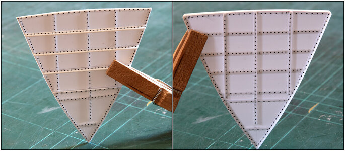
Lots of decal rivets that are now very dominantly visible. But just wait.........
The port side of the hull will be completely furnished, including hull plates.
The starboard side is pre-drilled for the rivets:
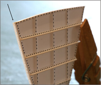
See the arrow at the side of the L-profile.
Then I looked for suitable paint.
Did an air-brush test with Vallejo Model Color, but it is too thick. Then the rivets are almost invisible.
It turned out, partly on the advice of Henk @Henk Liebre , that I should have a thinner Air:
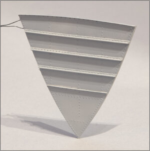
The frontside. Now they remain subtly visible. The widest part is 72 mm, the height 78 mm.
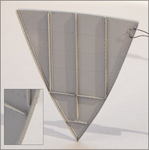
The backside. With the insert detail picture with the pre-drilled holes.
I'm not cutting the bulkhead in half yet. I'm going to make the frames 52, 53 and 54 first. If I can align it neatly and make it fit with an intermediate floor, then I will decide on the go or no-go.
I realize more and more that it is becoming complex in terms of construction.
I still have to look at some details for those 3 frames, because I cannot get everything from the old drawings.
The keelson lies on the 'retaining frames' that partly merge with the regular frames. It is not yet clear to me which side they are both facing. Which parts of the two L's come together. Will it be a right-angled Z or a U? Later I will also clarify this part with pictures.
I also need to take a closer look at the connection with the deck beam and knee piece.
Next week a visit to the Balder. Actually today with the storm it was not responsible to leave on the motorcycle.
Regards, Peter

Lots of decal rivets that are now very dominantly visible. But just wait.........
The port side of the hull will be completely furnished, including hull plates.
The starboard side is pre-drilled for the rivets:

See the arrow at the side of the L-profile.
Then I looked for suitable paint.
Did an air-brush test with Vallejo Model Color, but it is too thick. Then the rivets are almost invisible.
It turned out, partly on the advice of Henk @Henk Liebre , that I should have a thinner Air:

The frontside. Now they remain subtly visible. The widest part is 72 mm, the height 78 mm.

The backside. With the insert detail picture with the pre-drilled holes.
I'm not cutting the bulkhead in half yet. I'm going to make the frames 52, 53 and 54 first. If I can align it neatly and make it fit with an intermediate floor, then I will decide on the go or no-go.
I realize more and more that it is becoming complex in terms of construction.
I still have to look at some details for those 3 frames, because I cannot get everything from the old drawings.
The keelson lies on the 'retaining frames' that partly merge with the regular frames. It is not yet clear to me which side they are both facing. Which parts of the two L's come together. Will it be a right-angled Z or a U? Later I will also clarify this part with pictures.
I also need to take a closer look at the connection with the deck beam and knee piece.
Next week a visit to the Balder. Actually today with the storm it was not responsible to leave on the motorcycle.
Regards, Peter
I love this result
Very nice Peter. The whole thing looks very promising and convincing.
I love the painting bulkhead. I would paint the shades (is it possible in general???) on revet head to outline them. Also, I am thinking of possibilities to make the frame already cut in half, and glue both sides lightly in a few spots. Then it should be easier to remove. Or I could be just wrong.'m not cutting the bulkhead in half yet. I'm going to make the frames 52, 53 and 54 first. If I can align it neatly and make it fit with an intermediate floor, then I will decide on the go or no-go.
- Joined
- Aug 8, 2019
- Messages
- 5,575
- Points
- 738

Accurate as always. Love the tiny details and painting. Some extra rust or weathering to make it alive? 
If I may make a suggestionabout the plans you have, don't cut the frames in half. But glue, I understood there are a lot of these frames, the even numbered frames to the starboard side. And glue the uneven numbered ones on the port side. That way you still maintain a stable situation When opening the hull. Just an idea I got when I saw your frame and that sawing through, as you indicated, does little good.
If I may make a suggestionabout the plans you have, don't cut the frames in half. But glue, I understood there are a lot of these frames, the even numbered frames to the starboard side. And glue the uneven numbered ones on the port side. That way you still maintain a stable situation When opening the hull. Just an idea I got when I saw your frame and that sawing through, as you indicated, does little good.
Thanks, Uwe. I am also happy with the results.I love this result
Regards, Peter
You also thanks, Paul. It is the start that I can build on. With the next frame I hope to show something that can be recognized as the bow.Very nice Peter. The whole thing looks very promising and convincing.
Regards, Peter
Thanks for thinking along with me, Jim.I love the painting bulkhead. I would paint the shades (is it possible in general???) on revet head to outline them. Also, I am thinking of possibilities to make the frame already cut in half, and glue both sides lightly in a few spots. Then it should be easier to remove. Or I could be just wrong.
I cut the test bulkhead in half and outlined them. But that was wobbling a lot and difficult to line both parts in both directions.
A lot of possibilities went through my head.
Fitst I will test the ‘flow’ of the first 4 frames. Just dry-fit. To get a impression of the dimensions and shapes.
Because the complete internal construction but be fitted. Also with some longitudinal profiles.
So, first a in between secured step.
But feel free to vent opinions. It’s for me also completely new to invent almost everything.
Regards, Peter
You also thank for thinking with me, Stephan. But sliding in the even-starboard frames into the uneven-portside frames will give a problem with the deck rounding. Or I must cut the curved top of the frames.Accurate as always. Love the tiny details and painting. Some extra rust or weathering to make it alive?
If I may make a suggestionabout the plans you have, don't cut the frames in half. But glue, I understood there are a lot of these frames, the even numbered frames to the starboard side. And glue the uneven numbered ones on the port side. That way you still maintain a stable situation When opening the hull. Just an idea I got when I saw your frame and that sawing through, as you indicated, does little good.
And the keelson is laying on the ‘retaining frames’ upwards from the keel, which is also the base of the floors.
The fish holds where separated in the middle of the ship with a wall.
And in the middle of the deck are 2 L-profile over almost the whole length of the ship. All those beams will be placed to show the complete internal structure.
So, I think even more problems to solve with your idea.
I hope to post more of the old drawings soon. I'm busy with the permissions.
PS: No no, no weathering. The ship will be newly build on the yard. Former Alfa Romeo’s where already rusting in the folder.
Regards, Peter
Last edited:
Hi Peter,
Can you mirror the vertical L profile to both ships sides and split the frame between them. Offcourse this is a little concession to the original but you will avoid the wobbly frames. If you split the hull you won t notice it that much and if you combine two halves you don t see it.
Can you mirror the vertical L profile to both ships sides and split the frame between them. Offcourse this is a little concession to the original but you will avoid the wobbly frames. If you split the hull you won t notice it that much and if you combine two halves you don t see it.
- Joined
- Sep 3, 2021
- Messages
- 5,197
- Points
- 738

Already shared the idea with you on WhatsApp, but upon request: you could consider to have both stem and stern being an integral part of one half of the model. Say from the fwd watertight bulkhead to the bow and from the aft watertight bulkhead to the transom. It might give you a little more rigidity and less vulnerability of stem- and stern parts.
The opposite half of the hull would then slide into place in between those two "extensions".
Drawback: your intended assembly method needs to be revised...
The opposite half of the hull would then slide into place in between those two "extensions".
Drawback: your intended assembly method needs to be revised...
Good morning Peter. Wow! Just wow. This is going to be legendary. Cheers GrantWatertight bulkhead 51 is ready:
View attachment 404089
Lots of decal rivets that are now very dominantly visible. But just wait.........
The port side of the hull will be completely furnished, including hull plates.
The starboard side is pre-drilled for the rivets:
View attachment 404090
See the arrow at the side of the L-profile.
Then I looked for suitable paint.
Did an air-brush test with Vallejo Model Color, but it is too thick. Then the rivets are almost invisible.
It turned out, partly on the advice of Henk @Henk Liebre , that I should have a thinner Air:
View attachment 404091
The frontside. Now they remain subtly visible. The widest part is 72 mm, the height 78 mm.
View attachment 404092
The backside. With the insert detail picture with the pre-drilled holes.
I'm not cutting the bulkhead in half yet. I'm going to make the frames 52, 53 and 54 first. If I can align it neatly and make it fit with an intermediate floor, then I will decide on the go or no-go.
I realize more and more that it is becoming complex in terms of construction.
I still have to look at some details for those 3 frames, because I cannot get everything from the old drawings.
The keelson lies on the 'retaining frames' that partly merge with the regular frames. It is not yet clear to me which side they are both facing. Which parts of the two L's come together. Will it be a right-angled Z or a U? Later I will also clarify this part with pictures.
I also need to take a closer look at the connection with the deck beam and knee piece.
Next week a visit to the Balder. Actually today with the storm it was not responsible to leave on the motorcycle.
Regards, Peter
- Joined
- Sep 22, 2023
- Messages
- 238
- Points
- 213

Stai ottenendo dei risultati eccezionali. Dei pezzi perfetti.Watertight bulkhead 51 is ready:
View attachment 404089
Lots of decal rivets that are now very dominantly visible. But just wait.........
The port side of the hull will be completely furnished, including hull plates.
The starboard side is pre-drilled for the rivets:
View attachment 404090
See the arrow at the side of the L-profile.
Then I looked for suitable paint.
Did an air-brush test with Vallejo Model Color, but it is too thick. Then the rivets are almost invisible.
It turned out, partly on the advice of Henk @Henk Liebre , that I should have a thinner Air:
View attachment 404091
The frontside. Now they remain subtly visible. The widest part is 72 mm, the height 78 mm.
View attachment 404092
The backside. With the insert detail picture with the pre-drilled holes.
I'm not cutting the bulkhead in half yet. I'm going to make the frames 52, 53 and 54 first. If I can align it neatly and make it fit with an intermediate floor, then I will decide on the go or no-go.
I realize more and more that it is becoming complex in terms of construction.
I still have to look at some details for those 3 frames, because I cannot get everything from the old drawings.
The keelson lies on the 'retaining frames' that partly merge with the regular frames. It is not yet clear to me which side they are both facing. Which parts of the two L's come together. Will it be a right-angled Z or a U? Later I will also clarify this part with pictures.
I also need to take a closer look at the connection with the deck beam and knee piece.
Next week a visit to the Balder. Actually today with the storm it was not responsible to leave on the motorcycle.
Regards, Peter
You are getting great results. Perfect pieces.

