Better to recognize you ..... I will get used to them / thisHaha, you have to, Uwe. At least for the next .. years!
But is this one better / more specific?
Regards, Peter
-

Win a Free Custom Engraved Brass Coin!!!
As a way to introduce our brass coins to the community, we will raffle off a free coin during the month of August. Follow link ABOVE for instructions for entering.
-

PRE-ORDER SHIPS IN SCALE TODAY!
The beloved Ships in Scale Magazine is back and charting a new course for 2026!
Discover new skills, new techniques, and new inspirations in every issue.
NOTE THAT OUR FIRST ISSUE WILL BE JAN/FEB 2026
You are using an out of date browser. It may not display this or other websites correctly.
You should upgrade or use an alternative browser.
You should upgrade or use an alternative browser.
BALDER, Vlaardingen Herring Lugger from 1912, scratch build scale 1:50 Plate-On-Frame
- Thread starter Peter Voogt
- Start date
- Watchers 65
Yes! Being able to assemble the entire frames/bulkheads in Fushion, including the deck round:
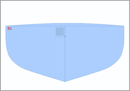
At the largest bulkhead 31 I added the curve that corresponds to the old drawing of the main frame. I copy that curve to each subsequent bulkhead that I prepare. And in the next step I reduce it to the width of that bulkhead. Then the deck radius is proportionately the same for each bulkhead.
I can export each created bulkhead with a fixed frame as a digital file. In this case I use the TIFF format because it has lossless compression.
Here are 4 bulkheads as an example:
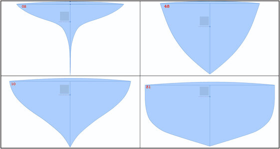
I copied the 3D plane logo. I collect all the bulkheads in Photoshop into separate layers. And via that logo I can organize all the frames and check them together with the export frame for the same resolution. And then all print in the same resolution.
These will be the molds on which I will assemble the frames.
In Fusion, according to a member of the Dutch forum is in Fushion function "Drawing from Design" to make a print in scale, but I (also) have to make an extra study of that. For the time being, I can now do it fairly quickly with little effort and with my Photoshop knowledge.
I removed also the draw points of each bulkheads that is ready.
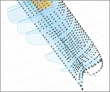
It slowly becomes a slightly less busy image.
Regards, Peter

At the largest bulkhead 31 I added the curve that corresponds to the old drawing of the main frame. I copy that curve to each subsequent bulkhead that I prepare. And in the next step I reduce it to the width of that bulkhead. Then the deck radius is proportionately the same for each bulkhead.
I can export each created bulkhead with a fixed frame as a digital file. In this case I use the TIFF format because it has lossless compression.
Here are 4 bulkheads as an example:

I copied the 3D plane logo. I collect all the bulkheads in Photoshop into separate layers. And via that logo I can organize all the frames and check them together with the export frame for the same resolution. And then all print in the same resolution.
These will be the molds on which I will assemble the frames.
In Fusion, according to a member of the Dutch forum is in Fushion function "Drawing from Design" to make a print in scale, but I (also) have to make an extra study of that. For the time being, I can now do it fairly quickly with little effort and with my Photoshop knowledge.
I removed also the draw points of each bulkheads that is ready.

It slowly becomes a slightly less busy image.
Regards, Peter
Last edited:
All 54 half frames/bulkheads mirrored and provided with the deck round:
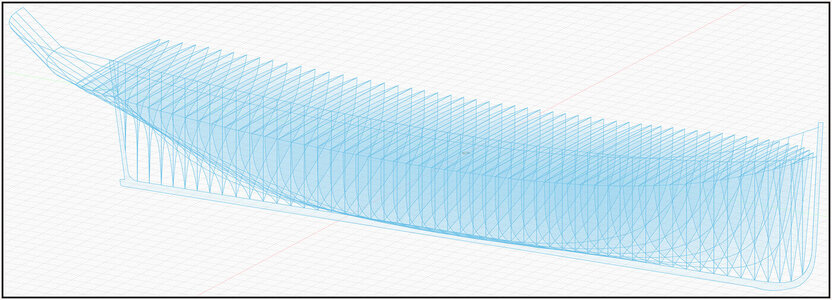
The lines of the keel and the bulwark were added to get a more complete picture.
With the loft applied:
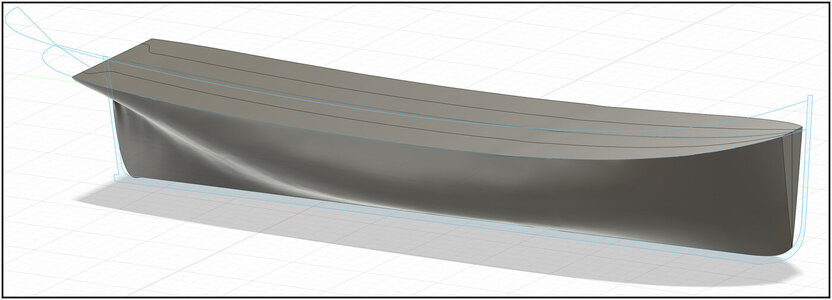
And diagonally from behind:
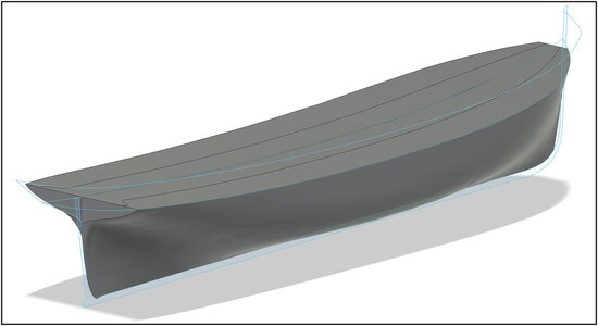
I have not (yet) managed to achieve a nice connection to the keel and stern. But that's not my point. It's about the flow of the bulkheads.
Then all individual bulkheads were exported as TIFF. Started calibrating to 1:50 scale in Photoshop:
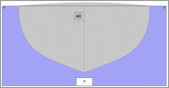
Using a separate layer in Photoshop, I also draw 2 frames for each bulkhead. Frame A is 16 cm wide and up to deck height. That becomes the supporting construction template and cut in half on the center line. Frame B is for cutting out so that the template can be placed around the construction beam, with a recess of 1 mm to slide over the keel.
A picture says more than 100 words:
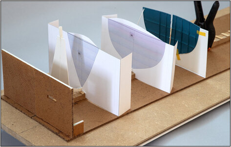
Here are templates 40 and 51 in place on the construction jig.
The gray-blue parts must be cut out carefully. I build the relevant frames on that.
Now prepare all 54 paper molds.
I use these paper molds to ultimately make the polystyrene molds with which I will actually build.
Regards, Peter

The lines of the keel and the bulwark were added to get a more complete picture.
With the loft applied:

And diagonally from behind:

I have not (yet) managed to achieve a nice connection to the keel and stern. But that's not my point. It's about the flow of the bulkheads.
Then all individual bulkheads were exported as TIFF. Started calibrating to 1:50 scale in Photoshop:

Using a separate layer in Photoshop, I also draw 2 frames for each bulkhead. Frame A is 16 cm wide and up to deck height. That becomes the supporting construction template and cut in half on the center line. Frame B is for cutting out so that the template can be placed around the construction beam, with a recess of 1 mm to slide over the keel.
A picture says more than 100 words:

Here are templates 40 and 51 in place on the construction jig.
The gray-blue parts must be cut out carefully. I build the relevant frames on that.
Now prepare all 54 paper molds.
I use these paper molds to ultimately make the polystyrene molds with which I will actually build.
Regards, Peter
Last edited:
Brilliant!
Thank you, Paul. I still find it unimaginable that all this is possible with one 111-year-old drawing made by hand.Brilliant!
Regard, Peter
That's not necessary, Stephan. With a simple action I have the right size in Photoshop and I can do all the extras with it. And then a TIFF is much more useful than a PDF.I convert the drawing in AutoCAD to pdf in scale. It is very simpel to do. I can explain. Just call me when you have time.
Regards, Peter
- Joined
- Aug 8, 2019
- Messages
- 5,573
- Points
- 738

Is that accurate?That's not necessary, Stephan. With a simple action I have the right size in Photoshop and I can do all the extras with it. And then a TIFF is much more useful than a PDF.
Regards, Peter
The most accurate as possible in this situation. But you have to know what you do. (In resolution till 3 digits behind the comma)Is that accurate?
A PDF is for exchange for document where the recipient cannot do anything about the layout made up by the author. Strange that that format is used for drawings. But if you only give a print command after the export, then it is no problem.
Regards, Peter
Last edited:
I love your methodical approach to modeling, this is something I am badly missing...but developing 
Thanks, Jim. Most appreciated. A bit of an old professional deformation.I love your methodical approach to modeling, this is something I am badly missing...but developing
as long as it does, you never know ……but developing
Regards, Peter
Enough drawing, time to further adjust the building jig to start building.
2 pieces of drawing of the line plan are glued to the 2 tiltable parts, along the construction beam (see A+A)
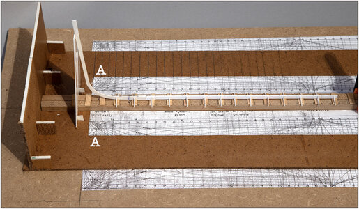
Both aligned with each other, of course.
Then I can place a template on the correct line, in this case for frame 51:
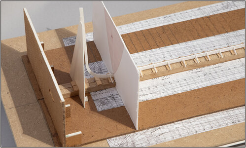
Now it’s still one piece, but soon it will be cut in half. I can align both parts perpendicular to the construction beam.
Also glued on the base plate are 2 pieces of drawing of the line plan (see B+B):
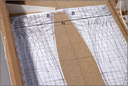
These are glued in such a way that I can place the tiltable parts on them in such a way that they both have a 1.5 degree angle. Because the keel slopes 1.5 degrees from front to back.
The white arrow shows that the edge of the base plate is sloping relative to the bottom of the tiltable part.
Now the two lines for frame 51 are in line with each other and are therefore perpendicular to the waterline. They are tilted forward by 1.5 degrees relative to the keel.
I can later align the half molds on these lines:
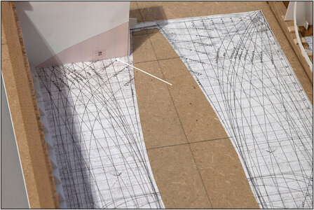
See white arrow, the paper version is for the image placed slightly next to the line.
And I can also align the top of the frame to deck height, the line just to the right of the arrowhead.
First cut out the part of the bulkhead from the template made in Photoshop. I will build the frame on that part and a 2nd print.
Then cut both the frame and the mold in half.
That's the theory. Now on to a practical test.......
Regards, Peter
2 pieces of drawing of the line plan are glued to the 2 tiltable parts, along the construction beam (see A+A)

Both aligned with each other, of course.
Then I can place a template on the correct line, in this case for frame 51:

Now it’s still one piece, but soon it will be cut in half. I can align both parts perpendicular to the construction beam.
Also glued on the base plate are 2 pieces of drawing of the line plan (see B+B):

These are glued in such a way that I can place the tiltable parts on them in such a way that they both have a 1.5 degree angle. Because the keel slopes 1.5 degrees from front to back.
The white arrow shows that the edge of the base plate is sloping relative to the bottom of the tiltable part.
Now the two lines for frame 51 are in line with each other and are therefore perpendicular to the waterline. They are tilted forward by 1.5 degrees relative to the keel.
I can later align the half molds on these lines:

See white arrow, the paper version is for the image placed slightly next to the line.
And I can also align the top of the frame to deck height, the line just to the right of the arrowhead.
First cut out the part of the bulkhead from the template made in Photoshop. I will build the frame on that part and a 2nd print.
Then cut both the frame and the mold in half.
That's the theory. Now on to a practical test.......
Regards, Peter
Last edited:
…..OH Boy….!Enough drawing, time to further adjust the building jig to start building.
2 pieces of drawing of the line plan are glued to the 2 tiltable parts, along the construction beam (see A+A)
View attachment 402338
Both aligned with each other, of course.
Then I can place a template on the correct line, in this case for frame 51:
View attachment 402340
Now it’s still one piece, but soon it will be cut in half. I can align both parts perpendicular to the construction beam.
Also glued on the base plate are 2 pieces of drawing of the line plan (see B+B):
View attachment 402341
These are glued in such a way that I can place the tiltable parts on them in such a way that they both have a 1.5 degree angle. Because the keel slopes 1.5 degrees from front to back.
The white arrow shows that the edge of the base plate is sloping relative to the bottom of the tiltable part.
Now the two lines for frame 51 are in line with each other and are therefore perpendicular to the waterline. They are tilted forward by 1.5 degrees relative to the keel.
I can later align the half molds on these lines:
View attachment 402342
See white arrow, the paper version is for the image placed slightly next to the line.
And I can also align the top of the frame to deck height, the line just to the right of the arrowhead.
First cut out the part of the bulkhead from the template made in Photoshop. I will build the frame on that part and a 2nd print.
Then cut both the frame and the mold in half.
That's the theory. Now on to a practical test.......
Regards, Peter
 Cheers Grant
Thanks for your optimistic response, Grant.…..OH Boy….!. I know you know what you are doing- I’m lost
Cheers Grant
Well......I have to think about a lot of things to get hopefully an acceptable result later. A lot of thinking ahead.
Experiments will soon show whether it works
Regards, Peter
In the previous post I already mentioned the bulkhead 51. With a reason. The stern is complex to make. That's why I start at the bow. To gain experience while working backwards.
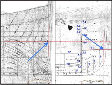
To clarify where I'm going to start, first some cut-outs of drawings:
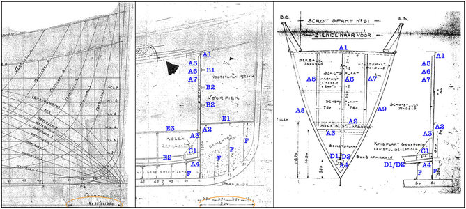
On the left the line plan that I also used when drawing in Fushion, in the middle the drawing of the 'Construction Plan for a Logger Ship" from the aforementioned shipyard A. de Jong and on the right the detailed drawings for the watertight bulkheads. All drawings are part of the files that I received from the SZB.
This concerns the bulkhead/frames 51 to 54, where 51 is the watertight bulkhead. That bulkhead becomes my starting point. I can align the other frames on that bulkhead.
First major difference:-
On the lines plan the dimension between bulkhead 51 and waterline point on the keel/bow frame is 1550 (mm = 1.55 mtr), see circle at the bottom.
On the Construction plan this dimension is 1500.
To process all dimensions during construction, I have to take the dimensions on the line plan as a starting point.
I have to apply to bulkhead 51:
-the L-profiles A1 to A9
-the T-profiles B1 to B3
And take into account the later application:
-Knee plate C1
-longitudinal profiles D1 and D2
-floor plates E1, E2 and E3
I am still discussing with the Balder technicians whether the 'vrangen' F has also been applied to the Balder. This is not clearly visible in an old restoration photo. I think so under the 'voorpiek', because that's where they keep the cement in place.
Got started! After almost 2 months of preparation.
Using the drawn bulkhead, cut the shape from 0.13mm/.005" sheet.
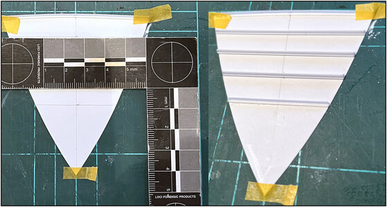
First apply L-profile A1 to the top edge of the front.
Plotted the horizontal lines and applied the T-profiles B1 to B3.
The L-profiles also applied to the rear:
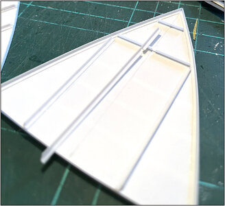
The middle vertical one is attached over the horizontal profile with a corresponding recess.
All profiles installed:
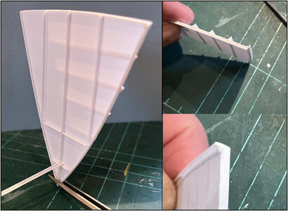
The ends of the profiles are all set or filed in the corners of the curve of the hull and deck.
At the bottom left, place 1 of the 2 L-profiles on the horizontal profile. These will soon run all the way across the frames to watertight bulkhead 39.
Next step: applying the rivets.
Regards, Peter
To clarify where I'm going to start, first some cut-outs of drawings:

On the left the line plan that I also used when drawing in Fushion, in the middle the drawing of the 'Construction Plan for a Logger Ship" from the aforementioned shipyard A. de Jong and on the right the detailed drawings for the watertight bulkheads. All drawings are part of the files that I received from the SZB.
This concerns the bulkhead/frames 51 to 54, where 51 is the watertight bulkhead. That bulkhead becomes my starting point. I can align the other frames on that bulkhead.
First major difference:-
On the lines plan the dimension between bulkhead 51 and waterline point on the keel/bow frame is 1550 (mm = 1.55 mtr), see circle at the bottom.
On the Construction plan this dimension is 1500.
To process all dimensions during construction, I have to take the dimensions on the line plan as a starting point.
I have to apply to bulkhead 51:
-the L-profiles A1 to A9
-the T-profiles B1 to B3
And take into account the later application:
-Knee plate C1
-longitudinal profiles D1 and D2
-floor plates E1, E2 and E3
I am still discussing with the Balder technicians whether the 'vrangen' F has also been applied to the Balder. This is not clearly visible in an old restoration photo. I think so under the 'voorpiek', because that's where they keep the cement in place.
Got started! After almost 2 months of preparation.
Using the drawn bulkhead, cut the shape from 0.13mm/.005" sheet.

First apply L-profile A1 to the top edge of the front.
Plotted the horizontal lines and applied the T-profiles B1 to B3.
The L-profiles also applied to the rear:

The middle vertical one is attached over the horizontal profile with a corresponding recess.
All profiles installed:

The ends of the profiles are all set or filed in the corners of the curve of the hull and deck.
At the bottom left, place 1 of the 2 L-profiles on the horizontal profile. These will soon run all the way across the frames to watertight bulkhead 39.
Next step: applying the rivets.
Regards, Peter
Last edited:
Wow Peter, fantastic work. As usual I'm late to the party but so glad I made it. Your approach to modeling the hull surface looks to be spot on. Over the years I have done quite a bit of surface modeling using field data topographic shots to figure dirt quantities, excavation, backfill haul off etc. Occasionally I would set a scale expansion factor say in the z direction to help spot any abnormalities. Sometimes subtle irregularities will show themselves, just a thought. What I see in your 3d surfaces look really smooth though. I think you have a unique and fascinating scratch build going here. Thanks for sharing.
PS now I understand your avatar.
PS now I understand your avatar.
- Joined
- Sep 22, 2023
- Messages
- 238
- Points
- 213

Ciao Peter.
Il tuo lavoro con Fusion è impressionante sei veramente bravo.
Hello Peter.
Your work with Fusion is impressive, you're really good.
Il tuo lavoro con Fusion è impressionante sei veramente bravo.
Hello Peter.
Your work with Fusion is impressive, you're really good.
Hi Daniel. Thanks for the compliments and visit. I am glad you found the log and your interest for the build. Still seat available.Wow Peter, fantastic work. As usual I'm late to the party but so glad I made it. Your approach to modeling the hull surface looks to be spot on. Over the years I have done quite a bit of surface modeling using field data topographic shots to figure dirt quantities, excavation, backfill haul off etc. Occasionally I would set a scale expansion factor say in the z direction to help spot any abnormalities. Sometimes subtle irregularities will show themselves, just a thought. What I see in your 3d surfaces look really smooth though. I think you have a unique and fascinating scratch build going here. Thanks for sharing.
PS now I understand your avatar.
Regards, Peter
Thanks, Alessandro. I am also happy with the result. Hoped in advance, but certainly not expected.Ciao Peter.
Il tuo lavoro con Fusion è impressionante sei veramente bravo.
Hello Peter.
Your work with Fusion is impressive, you're really good.
Regards, Peter
- Joined
- Sep 3, 2021
- Messages
- 5,196
- Points
- 738

You're absolutely right taking the line plan as your starting point, no questions asked.First major difference:-
On the lines plan the dimension between bulkhead 51 and waterline point on the keel/bow frame is 1550 (mm = 1.55 mtr), see circle at the bottom.
On the Construction plan this dimension is 1500.
To process all dimensions during construction, I have to take the dimensions on the line plan as a starting point.
With respect to the observed difference of 50mm; it appears that the 1550mm dimension is taken from the intersection of WL6 and (imaginery) frame 55, or your origin, to frame datum 51. The 1500 dimension seems to be taken from the intersection of the inner profile of the bow and the floor of the focsle to frame station 51. Unfortunately the construction drawing is not very clear, but it may be a plausible explanation.
