Ciao Joahn e ciao Peter.
Bravissimo Peter; Anch'io sono curioso di sapere il motivo di questa procedura. Mi ricollego alla domanda di Johan.
Io, ad esempio, ho dovuto creare più parti differenti della superficie dello scafo e poi unirle, perchè non riuscivo (nonostante nuemrosi tenativi a creare un'unica superficie dello scafo ni un'unica soluzione).
A questo punto mi sorge un altro quesito: Il tuo è già un volume o una superficie?
Well done Peter; I too am curious to know the reason for this procedure
I go back to Johan's question.For example, I had to create several different parts of the hull surface and then join them, because I couldn't (despite numerous attempts to create a single hull surface or a single solution).At this point another question arises: Is yours already a volume or a surface?
Hi Allessandro.
I'll first explain how I draw each frame. I'll show it, because I think that every programma has is own specific name for functions and objects:

I have specified 54 drawing panels (construction plane's) for all 54 frames on the longitudional Y axis. In accordance with their location that can be seen on the scanned line plan drawing.
First I make a 'Sketch' on a plane in 2D (just on the X and Z axis), in this case plane 52, and I draw the curved line (with the function see start of arrow 1st) between points A to J. Depending on where you place the points curved next to each other, the function itself draws a line with a certain curvature. You can adjust the curvature by moving the points (later). In my case I drew this curved line through the 'frame-52-points on the 7 water lines and 6 verticals.
Secondly, I draw with straight lines (with the function see beginning arrow 2nd) that start at point J. I can then make a straight 90 dgr angle at point K by first 'hovering' over point A, after which I am offered 2 auxiliary lines to draw the line. First secure at point K and then connect to A. By connecting these 3 lines, a 'profile' is created. Fusion then creates a color within the shape. If there is no coherent whole, then there is no color and you have to look for where no 'contact' has been made.
Now how I put together the 'loft':

After activating the "Create"+"Loft" function, I first choose the frame where I will start composing. In this case I click on the leftmost frame 27.
The sketch (see start arrow 1st) that I have made in Construction Plane-27 is then highlighted, the frame itself also lights up and the left 'Loft' frame becomes visible that I have 'Connected' Profile 1.
I then click on frame 28 (see arrow 2nd) and that also appears as 'connected' in the Loft frame.
Fushion then displays a box indicating "Select loft input" until you click "OK".
For the photo I then used the mouse to only point to the 3rd frame (see arrow 3th), causing the sketch with its 3 lines to light up.
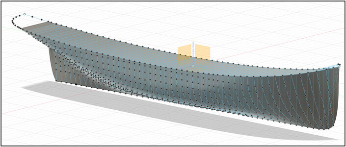
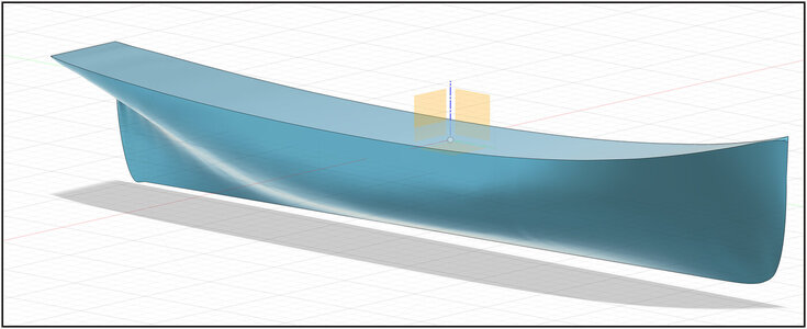
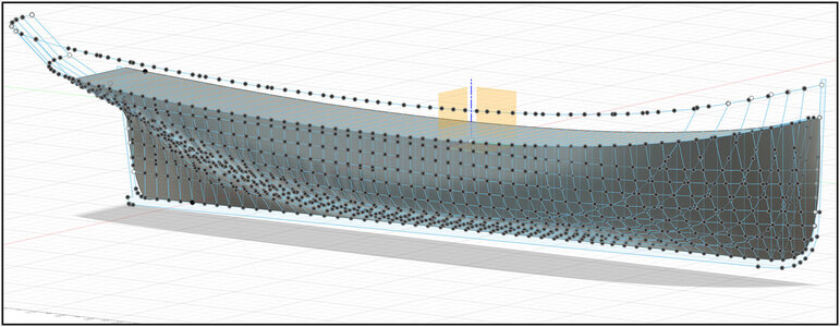
The loft function creates a skin over the outer lines of the selected frames. Because the skin ends in a point at the end, you get a closed whole.
At this point another question arises: Is yours already a volume or a surface?
I suppose it is a surface. Because, as I showed in a early post, you can create a bump or hollow by shifting a draw point.
Hopefully it is understandable.
Regards, Peter
 I am now at lesson 45.7f ……. or is it 7.8x ……


