BALDER, Vlaardingen Herring Lugger from 1912, scratch build scale 1:50 Plate-On-Frame

Hi Peter,
This sounds like a great plan. I am afraid that if it is finished it will not be in your living room but onboard the real Balder as an exhibit. This will become a grwat journey to follow.
Yes, Maarten, this is great journey with a lot of point to discover and plan.
And it would be no problem, but a big appreciation if they wanted the finished model in Vlaardingen in the Balder itself. We wil see in a few years ........ :)
Regards, Peter
 
Last edited:
In the meantime, 3D drawing continues.
Gradually I'm starting to understand some functionalities, but sometimes.........ggggggrrrrrr :confused:
In the meantime, my buddy is busy in AutoCAD:
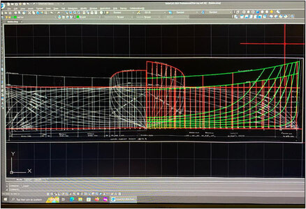
0063 AutoCAD.jpg
On the right side the drawn 'verticals' and deck + bulwark lines.

I am drawing the frames in a second way in Fushion:
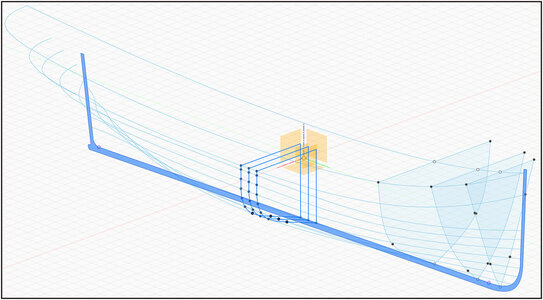
0062 Fushion.jpg
At the bow the 3 frames that I had already drawn earlier. These are officially called the index or distribution frames or 'Station lines' and are not the actual construction frames.
Now I have drawn the 7 water lines and placed them at height. While drawing, I inserted a drawing point at the location of the 54 building frames on each waterline. Via those waterlines I can now draw the shape of any desired frame vertically between the points on those waterlines.
In the cross-section view the position of frame-28 indicated in blue:
0065 Positie.jpg
Then I rotate the whole a bit in 3D view and see the shape of the frame emerge while drawing.
I have drawn the frames 27, 28 and 29 on the 3D drawing. I have left the drawing points in the frames visible here.

You must trace the lines of the old drawn line plan into the CAD program as if they were. During drawing and processing in the CAD program, you see that there are some inaccuracies on the old drawings. That is not surprising because those drawings were made by hand over 120 years ago using molds and stencils.
In CAD you can now see that the connected drawn lines sometimes do not flow neatly together.

Because I would like to get started with making the model frames, I compared CAD frame 28 with the old drawn main frame to be sure. Both placed them in 2 layers in Photoshop:
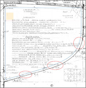
0064 Lagen.jpg
The blue line is the CAD frame. The shape deviates from the drawn frame in three places.
The curved lines in CAD are given a kind of pre-programmed rounding between your different drawing points. You can adjust that curvature afterwards. I now have to find out if this is because there are only 7 waterlines drawn. And I have to adjust the curve further.
Once I have drawn all 54 frame, I can connect them to each other to view the smooth flow between all frames.
So I'll have to work on it for a while before I can start building.
Because suppose, for example, If I have made the 3 old drawn waterproof frames and they do not match the shape of the other 51 CAD frames, then I have done the necessary work for nothing.
Let's see who gets 54 frame shapes first: me with Fushion or my buddy with AutoCAD. :)
Regards, Peter
 
Last edited:
The curved lines in CAD are given a kind of pre-programmed rounding between your different drawing points. You can adjust that curvature afterwards. I now have to find out if this is because there are only 7 waterlines drawn. And I have to adjust the curve further.
I think you're right in your assumption that it's due to 7 points, defining the curve, that you observe the deviations. To get a better (closer to drawing) curve you simply need more points of that curve, otherwise the CAD-program follows its own algorithms, or tweaking the results of the 7-point curves till the curve is right. You'll have to watch the resulting surface definition for bumps and dents though.
 
One might suspect Peter to have quite some Evergreen stocks...
I could buy a nice expensive model-kit from it. But with my nice old drawings I don’t need that. From that value I can buy another bunch of Evergreen profiles.
Then some more stocks, more profiles, more stocks, more profiles ……..
Then I am gonne sell Evergreen Profiles, sell stocks …….. and buy me a new motorcycle. Ooooo I have already…….
Regards, Peter
 
Last edited:
I think you're right in your assumption that it's due to 7 points, defining the curve, that you observe the deviations. To get a better (closer to drawing) curve you simply need more points of that curve, otherwise the CAD-program follows its own algorithms, or tweaking the results of the 7-point curves till the curve is right. You'll have to watch the resulting surface definition for bumps and dents though.
Yep, next step is also drawing all the ‘verticals’. That gives some more points. Then I can complete all the 54 frames and connect them with a digital hull.
And check the shape with the 12 index/Stationlines and the 3 old drawings of the watertight frames.
So, busy for the next ………..
Regards, Peter
 
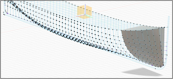
Starting to get the hang of Fusion 360. The wrong beginning has largely been thrown away. Now drawpoints have been placed on all 'waterlines', 'verticals' as well as the deck and bulwark at the position where the 54 frames will be located
I can now assemble the frames via these points:
0066 Fushion Voorschip.jpg
The front half is equipped with half frames.
Later an image without all those points. Somewhere there will be an option to do that in one go. Now I would have to do it per line.
Regards, Peter
 
The wrong beginning has largely been thrown away.
That's sound familiar :)

Your design is looking good. Did you also controll the distance between the waterlines and frames of the drawing of this is equal over the hole distance. In my drawing this wasn't the case. After correction of the square frame a lot of problems where solved. AutoCAD is much more accurate then a drawing. I think I started 4 times again drawing.
 
That's sound familiar :)
Your design is looking good. Did you also controll the distance between the waterlines and frames of the drawing of this is equal over the hole distance. In my drawing this wasn't the case. After correction of the square frame a lot of problems where solved. AutoCAD is much more accurate then a drawing. I think I started 4 times again drawing.
Hi Stephan. The drawings have some imperfections. But that's logical for hand drawing from 110 years old. But there are written measures:
1697044837633.png
I can slice the drawing point in the program to get lines with a nice flow in comparison with the 2 besides.
When I have al the frames I can make a 'loft' between all the frames and see the complete flow of the hull.
But when I am at that point, I will post some print-screens.
Regards, Peter
 
Starting to get the hang of Fusion 360. The wrong beginning has largely been thrown away. Now drawpoints have been placed on all 'waterlines', 'verticals' as well as the deck and bulwark at the position where the 54 frames will be located
I can now assemble the frames via these points:
View attachment 399479
The front half is equipped with half frames.
Later an image without all those points. Somewhere there will be an option to do that in one go. Now I would have to do it per line.
Regards, Peter
I envy (in a good way) your ability to understand 3D graphics programs. I don't know anything about this. I would love to learn...
 
I envy (in a good way) your ability to understand 3D graphics programs. I don't know anything about this. I would love to learn...
Thanks, Jim.
Once you know the basics...... :rolleyes:
after watching some videos in which they just don't show what you need....... Redface
just start and start again....... Sick
throw away what doesn't work and then suddenly a bright spot and you realize what works. :)
It must be because of my work, as we also did investigate till the final 'bingo'.
Now I can make progress. :p
Regards, Peter
...waiting for my 'Bingo' or Aha... moment. ;) :)
 
All 3D-tools I used invariably had an incredibly steep learning curve and that didn't get any better once more functionality was added to these tools. To add to misery, once you've gotten used the intricacies of one tool, it became even harder to transition to another 3D-tool
...Bingo!! ;) Thank you.
 
:oops:All 3D-tools I used invariably had an incredibly steep learning curve and that didn't get any better once more functionality was added to these tools. To add to misery, once you've gotten used the intricacies of one tool, it became even harder to transition to another 3D-tool
...Bingo!! ;) Thank you.
I initially started with 'self-study' in Photoshop. Until I had a week of lessons at the Grafisch Lyceum through my work. 'A world' opened up for me.:)
Now get started with 'self-study' in Fusion. I am retired and am now opening up 'the world' through some video’s on the internet.:confused:
As I already wrote: the learning curve is inversely proportional to the shape of the Balder's hull.:D
The main keys: time&practice ….
Regards, Peter
Companies like ship, car- and aircraft manufacturers have specialized staff defining and refining the surface definitions of their products. It's definitely a specialism, requiring highly trained professionals.
Any "amateur" able to generate usable surfaces deserves quite some bonus points.
 
Sometimes you think, I'm well on my way. Just throw away an apparently empty point and then.........gggggrrrrr. :confused: Fortunately, Ctrl-Z (step back) also works here. :)
Once you have drawn a few frames, you can use the 'loft function' to pull some kind of sheet material over those frames. Then you can also see whether the shape runs smoothly.
It then turns out that those old drawings, as mentioned earlier, contain imperfections. Made the lines of the frames smoother by hand and then again.
Here is an example of the frames 47 to 54:
0067 Fushion Hull.jpg
I still have to make the connection to the bow.
The corner points of the lines of the frames should connect to the drawing points on the lines of the keel and deck. It was also quite a puzzle to get that done, because you always have to consider in which of the 3 drawing areas you are working. The deck still must have the deck curves, but that will come later.
But it's still fun, especially now that the results are out.
Regards, Peter
 
Back
Top