WYSIWYGHe got a green mat, for sure. See post #3
-

Win a Free Custom Engraved Brass Coin!!!
As a way to introduce our brass coins to the community, we will raffle off a free coin during the month of August. Follow link ABOVE for instructions for entering.
-

PRE-ORDER SHIPS IN SCALE TODAY!
The beloved Ships in Scale Magazine is back and charting a new course for 2026!
Discover new skills, new techniques, and new inspirations in every issue.
NOTE THAT OUR FIRST ISSUE WILL BE JAN/FEB 2026
You are using an out of date browser. It may not display this or other websites correctly.
You should upgrade or use an alternative browser.
You should upgrade or use an alternative browser.
BALDER, Vlaardingen Herring Lugger from 1912, scratch build scale 1:50 Plate-On-Frame
- Thread starter Peter Voogt
- Start date
- Watchers 65
- Joined
- Sep 3, 2021
- Messages
- 5,196
- Points
- 738

It is conceivable that during the restaurations they opted for improving the corrosion protection by overlapping the sheets as shown in the RH picture. Conceivable, but that's all it is.Thanks, Johan.
About the lapjoints. As seen on the old drawing, they started with the sheet of the railing and then every lower sheets with the top over the bottom of the previous one:
View attachment 397282
But on the insert you can see that on the Balder this middle sheet has a overlap of the one above and below.
The Balder has been restored twice and some of the sheets have been replaced. Then I don't think they could have avoided deviating.
An advantage if I make a mistake later, I simply used a 'restoration pattern'.
And as I already indicated, no flanged edges on the Balder. But I did that to also try it out on this scale. Without them the transitions automatically become tighter.
Regards, Peter
Another thing which struck me was the triangular shaped openings between the lap-joined sheets and the skin flange of the frames; an open invitation for corrosion to start it's disastrous work. The good thing is it won't effect your build.
Already looking forward to the AL-FI declarations...
I have to remember in future this new term 'restoration pattern' - sounds good 
Yep Green most definitely…and Peter must have manyI think that you are really on a very good waylooking very promising
BTW: Which colour does your cutting mat has? I guess green based on the actual thesis by @Steef66
Nope, it’s my Admiral’s ScrapBook cutting mat, but I used it at most. I prefer a mat in see-green/see-blue, depending on what kind of light source is illuminated. I prefer the old natrium, because then you really don't know what the original color of the subject is. Any discussion about the correct color can be ended immediately.Yep Green most definitely…and Peter must have many
So my mat is purple-pink-orange with a hint of indefinable brown ………
Regards, Peter
- Joined
- Jan 9, 2020
- Messages
- 10,566
- Points
- 938

I find your thought process enlightening to say the least, Peter. This is why you turn out models like the Robert E. Lee, the Pocher Ducati and the Bluenose. The phrase "attention to detail" doesn't cut it when it comes to your work. I am not commenting much, because I have absolutely zero experience of the materials you are working with, but I am watching very carefully.
Thanks, Heinrich. You can process Evergeen in almost the same way as wood. Bending with heat, drill, file, sand, screw etc. You only need another type of glue.I find your thought process enlightening to say the least, Peter. This is why you turn out models like the Robert E. Lee, the Pocher Ducati and the Bluenose. The phrase "attention to detail" doesn't cut it when it comes to your work. I am not commenting much, because I have absolutely zero experience of the materials you are working with, but I am watching very carefully.
They have a huge variety to profiles, sheets etc:

EVERGREEN SCALE MODELS
EVERGREEN SCALE MODELS IS THE FOREMOST PRODUCER OF POLYSTYRENE STRIPS AND SHAPES FOR MODEL MAKERS ARCHITECTS, AND ARTISANS AS WELL AS THE OEM MARKET.
 evergreenscalemodels.com
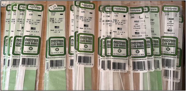
I only need a few more that correspond in size and profile to the dimensions of the old drawing, related to 1:50.
But Raboesch has also a great variety.
Regards, Peter
Hi Peter,Thanks, Heinrich. You can process Evergeen in almost the same way as wood. Bending with heat, drill, file, sand, screw etc. You only need another type of glue.
They have a huge variety to profiles, sheets etc:
I used it already for some parts on the Lee and the Bluenose and already have a nice collection:
EVERGREEN SCALE MODELS
EVERGREEN SCALE MODELS IS THE FOREMOST PRODUCER OF POLYSTYRENE STRIPS AND SHAPES FOR MODEL MAKERS ARCHITECTS, AND ARTISANS AS WELL AS THE OEM MARKET.evergreenscalemodels.com
View attachment 398215
I only need a few more that correspond in size and profile to the dimensions of the old drawing, related to 1:50.
But Raboesch has also a great variety.
Regards, Peter
Have you already informed Evergreen so they can increase the production?

You won't believe it, but they offered me shares for a fair price ……..Hi Peter,
Have you already informed Evergreen so they can increase the production?
Regards, Peter
- Joined
- Sep 22, 2023
- Messages
- 238
- Points
- 213

Ciao Peter.For those interested a little preview: in Fushion 360, drawn in the Y-line drawing (width), projected at the bow in the X-line (length) drawing, the first 5 Station Lines started from the bow. And transferred in the X-line drawing (length) in the length from the bow till midship:
View attachment 392305
When you know how to do ……. Then it is …… But before you know ……. RTFM
And the used lineplan:
View attachment 392310
(Source: Drawing from the SZB)
Now I have to flip the Y-line drawing to draw the 7 line till the stern.
Regards, Peter
Il tuo nuovo lavoro è interessantissimo.
Hai iniziato nel migliore dei modi. La lunga descrizione storica è molto gradita per me. Apprezzo molto gli approfondimenti di questo genere con foto e informazioni.
L'uso di un programma di disegno 3d (nel tuo caso Fushion360) lo renderà ancora più interessante ai miei occhi.
Spero che inserirai molte foto e spiegazioni al riguardo.
Hello Peter.
Your new job is very interesting.
You're off to a great start.
The long historical description is very welcome to me. I really appreciate insights like this with photos and information.
The use of a 3D drawing program (in your case Fushion360) will make it even more interesting in my eyes.
I hope you will post lots of photos and explanations about it.
Hi Alessandro.Ciao Peter.
Il tuo nuovo lavoro è interessantissimo.
Hai iniziato nel migliore dei modi. La lunga descrizione storica è molto gradita per me. Apprezzo molto gli approfondimenti di questo genere con foto e informazioni.
L'uso di un programma di disegno 3d (nel tuo caso Fushion360) lo renderà ancora più interessante ai miei occhi.
Spero che inserirai molte foto e spiegazioni al riguardo.
Hello Peter.
Your new job is very interesting.
You're off to a great start.
The long historical description is very welcome to me. I really appreciate insights like this with photos and information.
The use of a 3D drawing program (in your case Fushion360) will make it even more interesting in my eyes.
I hope you will post lots of photos and explanations about it.
I'm glad you appreciate my introduction.
Learning to work with a 3D CAD program takes a lot of time. As soon as there are more results, I will certainly post them. My hopes are partly based on a friend of mine who is entering the old line plan into AutopCAD. He works every day with AutoCAD at a shipyard where luxury yachts are developed and built.
So, hopefully soon more to post ……
Regards, Peter
- Joined
- Sep 22, 2023
- Messages
- 238
- Points
- 213

Aspetterò con interesse e curiosità.Hi Alessandro.
I'm glad you appreciate my introduction.
Learning to work with a 3D CAD program takes a lot of time. As soon as there are more results, I will certainly post them. My hopes are partly based on a friend of mine who is entering the old line plan into AutopCAD. He works every day with AutoCAD at a shipyard where luxury yachts are developed and built.
So, hopefully soon more to post ……
Regards, Peter
I will wait with interest and curiosity.
It was quiet on the yard for a while, but that's because I've made a start on the actual shipyard:
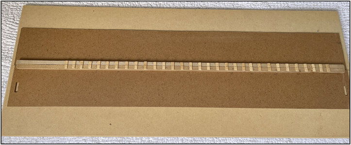
The keel is placed on the main beam with the cross beams. The base plate is inclined by 1.5 degrees, because on the old drawings the keel beam also slopes forward by 1.5 degrees.
Placed the bow section and laid the first part of the keel:

These parts are made of 0.5 mm thick sheet material and strips.
What's the point of those two cleats around the main beam?
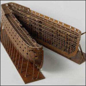
I sawed my Bluenose in half at the waterline because I wanted to build the interior and have it be visible.
This image also appeared in my Bluenose report:

The half-open lengthwise model.
In Paul's @dockattner report of the Kingfisher this model was mentioned:
So many things were going through my mind before starting to build my new model. I had already mentioned that I also wanted to build the entire original construction and interior of the Balder. That must be visible.
To avoid having to put the saw back in, it is best to take this into account in advance.
If you look closely, you will see the bow and keel parts consist of 2 lengthwise parts:
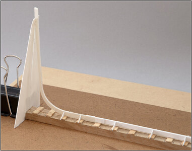
The bow and keel plates are temporarily connected.
If I remove both clamps, I can separate the 2 floor parts on my base plate:
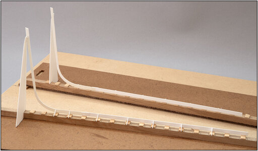
And the bow and keel parts got separated.
With a look from the front:
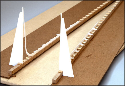
At the beginning of the left floor section you will see a small block. That's at the back too. Both floor parts slide over it so that I can always fix those parts against each other in the same position. Clamps on and I can continue building.
Now I first have to install the 2 test frames as a test to see whether what I have devised is actually workable.
My intention is to completely furnish and clad the starboard side. The port side remains open so that the construction remains visible.
In the meantime, we continue to draw...
Regards, Peter

The keel is placed on the main beam with the cross beams. The base plate is inclined by 1.5 degrees, because on the old drawings the keel beam also slopes forward by 1.5 degrees.
Placed the bow section and laid the first part of the keel:

These parts are made of 0.5 mm thick sheet material and strips.
What's the point of those two cleats around the main beam?
I sawed my Bluenose in half at the waterline because I wanted to build the interior and have it be visible.
This image also appeared in my Bluenose report:

The half-open lengthwise model.
In Paul's @dockattner report of the Kingfisher this model was mentioned:

So many things were going through my mind before starting to build my new model. I had already mentioned that I also wanted to build the entire original construction and interior of the Balder. That must be visible.
To avoid having to put the saw back in, it is best to take this into account in advance.
If you look closely, you will see the bow and keel parts consist of 2 lengthwise parts:

The bow and keel plates are temporarily connected.
If I remove both clamps, I can separate the 2 floor parts on my base plate:

And the bow and keel parts got separated.
With a look from the front:

At the beginning of the left floor section you will see a small block. That's at the back too. Both floor parts slide over it so that I can always fix those parts against each other in the same position. Clamps on and I can continue building.
Now I first have to install the 2 test frames as a test to see whether what I have devised is actually workable.
My intention is to completely furnish and clad the starboard side. The port side remains open so that the construction remains visible.
In the meantime, we continue to draw...
Regards, Peter
Last edited:
- Joined
- Aug 8, 2019
- Messages
- 5,573
- Points
- 738

This is a great look on a future build. A big WOW if you could achieve this. Because this is not a easy job and if somebody could do this, I think it's you.View attachment 398683
So many things were going through my mind before starting
View attachment 398686
WOW, you are off to a very good start, Peter,
Thanks, Stephan. I have to think a lot of steps ahead.This is a great look on a future build. A big WOW if you could achieve this. Because this is not a easy job and if somebody could do this, I think it's you.
Once I have taken both floorboards apart, I can tilt them a quarter turn so that the vertical inner side rests on the worktop. And I can build and align both halves neatly flat so that once they are upright again, they also connect neatly in the lengthwise direction. But of course I will clarify that with photos.

Regard, Peter
Thanks, Jim. When the start and the base are solid, then the rest ………WOW, you are off to a very good start, Peter,
Well, just what I answered Stephan, now it’s thinking a lot of steps ahead.
And I will probably have to make some adjustments, but that generally went well with the Bluenose.
Regard, Peter
Hi Peter,
That is some undertaking indeed.
Are you going to place some kitchen cling wrap between the parts you don't want to glue together?
Cheers,
Stephen.
That is some undertaking indeed.
Are you going to place some kitchen cling wrap between the parts you don't want to glue together?
Cheers,
Stephen.
Hi Stephen.Hi Peter,
That is some undertaking indeed.
Are you going to place some kitchen cling wrap between the parts you don't want to glue together?
Cheers,
Stephen.
I don't oversee everything yet, but everything starts with an idea and a start to implementation.
About wrapping: hopefully not and it will remain just gluing and imitation riveting.
Regards, Peter
Last edited:
Hi Peter,Hi Stephan.
I don't oversee everything yet, but everything starts with an idea and a start to implementation.
About wrapping: hopefully not and it will remain just gluing and imitation riveting.
Regards, Peter
The cling wrap idea was more for preventing accidental gluing of the 2 keel sides together, quite easy to do with thin wick in adhesive.
Cheers,
Stephen.


