...If the rudder is presented in such a filigree way, what would be the rudder mechanism itself? Just WOW!
-

Win a Free Custom Engraved Brass Coin!!!
As a way to introduce our brass coins to the community, we will raffle off a free coin during the month of August. Follow link ABOVE for instructions for entering.
-

PRE-ORDER SHIPS IN SCALE TODAY!
The beloved Ships in Scale Magazine is back and charting a new course for 2026!
Discover new skills, new techniques, and new inspirations in every issue.
NOTE THAT OUR FIRST ISSUE WILL BE JAN/FEB 2026
You are using an out of date browser. It may not display this or other websites correctly.
You should upgrade or use an alternative browser.
You should upgrade or use an alternative browser.
BALDER, Vlaardingen Herring Lugger from 1912, scratch build scale 1:50 Plate-On-Frame
- Thread starter Peter Voogt
- Start date
- Watchers 65
That rudder mechanism is very sophisticated ........If the rudder is presented in such a filigree way, what would be the rudder mechanism itself? Just WOW!
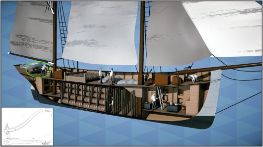
(Source:--> The virtual site of the Balder. <--)
Just a tiller on the king pin .......
To see the half-model, click 'STAP AAN BOORD', then 'HET LEVEN AAN BOORD'.
I just found this specific page long after my choice to build it this way.
Regards, Peter
Last edited:
It took 'some time and energy' to set the basis for the construction of the aft ship.
My point of view at the beginning of the build was to start at the front and then work backwards. In order to gain experience with the material. In retrospect, a good choice because now various curves come together with also laborious frames.
After having hung over the drawings for a considerable time, I decided to take frames 2 and 5 as a basis for further building. See these 2 numbers in the photo:
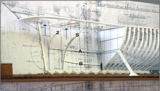
'A' is the middle longitudinal floor beam where the donkey boiler and the accommodation will be. This floor is supported in the middle by uprights that rest on the keelson 'B'. Compared to this drawing, it runs slightly, but the line drawing and the separate drawing of the bulkhead 14 are my starting points.
That keelson is only a (double) angle profile in this part between the watertight bulkhead 14 and frame 5. It runs slightly upwards to the rear. The floor beam runs from bulkhead 14 over all the cross floorbeams up to frame 2.
At frame 5 the (half) cross beam and upright are visible. From frame 5 towards bulkhead 14 the floor becomes wider. That is why the layout of the accommodation is built in a V. Which is visible in the combination drawing that I posted earlier.
The 2 arrows point to the openings that I will have to make later for the hatch to the storage space behind deck beam 2 and the skylight before deck beam 5. That is also why there is a small piece of middle beam under deck beams 2 and 5. 3 and 4 will also rest on it.
The connections between these 2 frames and 2 beams have already made it a solid whole:"
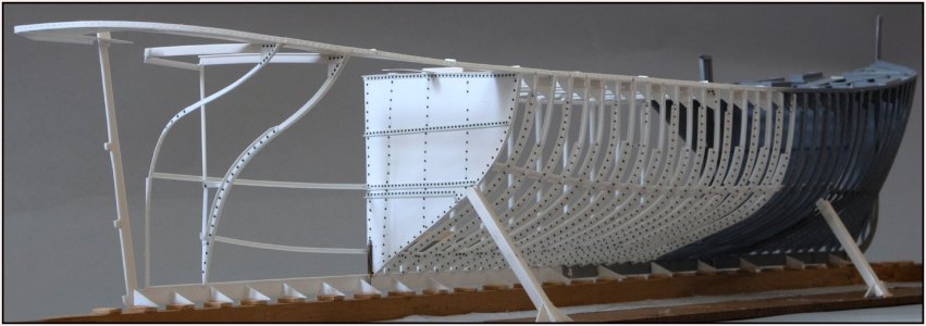
The stringer with waterway has immediately adopted the correct curvature of the sheer. A temporary upright has been placed under the middle of deck beam 5.
Everything also remains neatly straight:
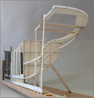
For the time being, theory and practice continue to run parallel.
What is now standing I can use to align the rest.
Regards, Peter
My point of view at the beginning of the build was to start at the front and then work backwards. In order to gain experience with the material. In retrospect, a good choice because now various curves come together with also laborious frames.
After having hung over the drawings for a considerable time, I decided to take frames 2 and 5 as a basis for further building. See these 2 numbers in the photo:

'A' is the middle longitudinal floor beam where the donkey boiler and the accommodation will be. This floor is supported in the middle by uprights that rest on the keelson 'B'. Compared to this drawing, it runs slightly, but the line drawing and the separate drawing of the bulkhead 14 are my starting points.
That keelson is only a (double) angle profile in this part between the watertight bulkhead 14 and frame 5. It runs slightly upwards to the rear. The floor beam runs from bulkhead 14 over all the cross floorbeams up to frame 2.
At frame 5 the (half) cross beam and upright are visible. From frame 5 towards bulkhead 14 the floor becomes wider. That is why the layout of the accommodation is built in a V. Which is visible in the combination drawing that I posted earlier.
The 2 arrows point to the openings that I will have to make later for the hatch to the storage space behind deck beam 2 and the skylight before deck beam 5. That is also why there is a small piece of middle beam under deck beams 2 and 5. 3 and 4 will also rest on it.
The connections between these 2 frames and 2 beams have already made it a solid whole:"

The stringer with waterway has immediately adopted the correct curvature of the sheer. A temporary upright has been placed under the middle of deck beam 5.
Everything also remains neatly straight:

For the time being, theory and practice continue to run parallel.
What is now standing I can use to align the rest.
Regards, Peter
Last edited:
Very nice sleek lines in the aft ship.
Very nice sleek lines in the aft ship.
Thanks Maarten en Stephan. These double curvature frames are of a different order than those already placed. With more complex lines where the making of the hull plates will also require the necessary attention.I agree with Maarten, in this stage it looks already like a masterpiece.
Regards, Peter
Hi Peter, I’m curious how you are preventing the frame stock from twisting while it is being bent/shaped? Does heat make the material stretchable in a controlled way? My apologies if this is reported elsewhere in you build report.
Thanks for this question, Paul. In my previous post I wrote this:Hi Peter, I’m curious how you are preventing the frame stock from twisting while it is being bent/shaped? Does heat make the material stretchable in a controlled way? My apologies if this is reported elsewhere in you build report.
This relates exactly to your question.In order to gain experience with the material.
For the most part I use 90 gr angle profile of 1.5x1.5 mm.
With the first bend, that '90 gr angle' works in such a way that it makes the bend both to the right and upwards. See pictures '1' and '2':

I do not make the bending happen in one movement, but I let it slide through my finger several times. Then some heat is added.
Your assumption is correct: Adding heat in a measured way is the magic word. After cooling, it retains its new shape.
I also have an electric water boiler with a metal wall. Sometimes I hold it against that for a while to bend it afterwards. An old-fashioned halogen lamp above my worktop also provides the necessary heat. I sometimes hold small pieces near it to warm them up. If you make the material too hot it will deform. Dipping a piece of profile in boiling water will result in a wobble .......
To get the bend that is visible in picture '2' flat again, I heat the upright wall of the profile a little and stretch it bit by bit. This will cause it to bend downwards again and after a while you will get a flat bend like in picture '3'. Because you cannot 'collapse' the flat side you have to stretch.
Actually it is not much different than bending brass or copper. Only with a much lower temperature. And here too it applies that bending back and forth too often takes away the strength from the material.
As my father often said: "Patience is a virtue."
Perhaps a long answer, but it may now give you more insight into the wonderful world of Evergeen editing.
Regards, Peter
Thanks Peter. Every material has its learning ‘curve’.Thanks for this question, Paul. In my previous post I wrote this:
This relates exactly to your question.
For the most part I use 90 gr angle profile of 1.5x1.5 mm.
With the first bend, that '90 gr angle' works in such a way that it makes the bend both to the right and upwards. See pictures '1' and '2':
View attachment 470031
I do not make the bending happen in one movement, but I let it slide through my finger several times. Then some heat is added.
Your assumption is correct: Adding heat in a measured way is the magic word. After cooling, it retains its new shape.
I also have an electric water boiler with a metal wall. Sometimes I hold it against that for a while to bend it afterwards. An old-fashioned halogen lamp above my worktop also provides the necessary heat. I sometimes hold small pieces near it to warm them up. If you make the material too hot it will deform. Dipping a piece of profile in boiling water will result in a wobble .......
To get the bend that is visible in picture '2' flat again, I heat the upright wall of the profile a little and stretch it bit by bit. This will cause it to bend downwards again and after a while you will get a flat bend like in picture '3'. Because you cannot 'collapse' the flat side you have to stretch.
Actually it is not much different than bending brass or copper. Only with a much lower temperature. And here too it applies that bending back and forth too often takes away the strength from the material.
As my father often said: "Patience is a virtue."
Perhaps a long answer, but it may now give you more insight into the wonderful world of Evergeen editing.
Regards, Peter
Continued a bit further with strengthening the aft.
Made the frame for the hatch of the storage room that connects the deck beam of frame 2 with deck beam 0 and rests on a piece of stringer plate:
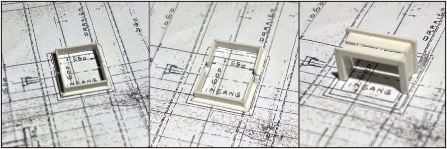
Left: 600x590 is in scale 12x11.8mm
Middle: Must be in 2 parts
Right: Check whether both parts are square and the same size.
In place together with frame and deck beam 0:
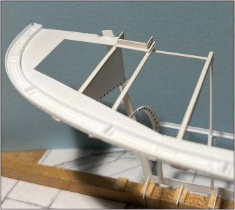
For the attentive viewer: on the model the rear of the frame is almost on deck beam 0. On the drawing of the previous photo more on the stringer plate. The frame distance on that drawing deviates slightly from that of the line drawing that I used in Fushion. Always a difference point that is always in the back of my mind.
On the line drawing it did not go further than the frame with deck beam 0.
While there are still 2 small frames behind the stern / rudder beam. To support the skin plates at the rounding. So back to Fushion and drew and printed those 2. These frames numbered -1 and -2.
After again the a lot of hours of fitting and measuring, these 2 were also made and placed:
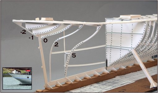
These two have a plate to fill between the deck beam and the frame. Also frame 0, which functions as the rear wall of the storage between that frame and frame 2.
From the stern where the rudder is attached, there is also a sloping profile to the middle of the rear of the deck. However, that profile is not directly on the stern.
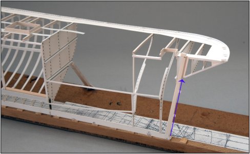
A half tube is first placed against the stern, against which the sloping piece of profile is located. See the top of the arrow. With the same in the port side part, that then forms the tube through which the rudder stock runs.
Together with the hull sheets that is applied around that tube, you then have a watertight seal.
Regards, Peter
Made the frame for the hatch of the storage room that connects the deck beam of frame 2 with deck beam 0 and rests on a piece of stringer plate:

Left: 600x590 is in scale 12x11.8mm
Middle: Must be in 2 parts
Right: Check whether both parts are square and the same size.
In place together with frame and deck beam 0:

For the attentive viewer: on the model the rear of the frame is almost on deck beam 0. On the drawing of the previous photo more on the stringer plate. The frame distance on that drawing deviates slightly from that of the line drawing that I used in Fushion. Always a difference point that is always in the back of my mind.
On the line drawing it did not go further than the frame with deck beam 0.
While there are still 2 small frames behind the stern / rudder beam. To support the skin plates at the rounding. So back to Fushion and drew and printed those 2. These frames numbered -1 and -2.
After again the a lot of hours of fitting and measuring, these 2 were also made and placed:

These two have a plate to fill between the deck beam and the frame. Also frame 0, which functions as the rear wall of the storage between that frame and frame 2.
From the stern where the rudder is attached, there is also a sloping profile to the middle of the rear of the deck. However, that profile is not directly on the stern.

A half tube is first placed against the stern, against which the sloping piece of profile is located. See the top of the arrow. With the same in the port side part, that then forms the tube through which the rudder stock runs.
Together with the hull sheets that is applied around that tube, you then have a watertight seal.
Regards, Peter
Last edited:
Just fantastic Peter. You have a gift for converting 2D into 3D.
- Joined
- Sep 3, 2021
- Messages
- 5,190
- Points
- 738

Being able to use a 3D modeling program is a definite plus; it allows you to modify and evaluate certain issues and nip the problem in the bud, instead of endlessly fiddling around with actual parts.
Drawback, if you're anything like me, it's too tempting to keep modifying, improving the model...
Drawback, if you're anything like me, it's too tempting to keep modifying, improving the model...
Last edited:
Just fantastic Peter. You have a gift for converting 2D into 3D.
Thanks, Paul and Johan. It’s still fun to figure out how this model must be build. With the help of all kind of old fashion and new techniques.Being able to use a 3D modeling program is a definite plus; it allows you to modify and evaluate certain issues and nip the problem in the bud, instead of endlessly fiddling around with actual parts.
Haha, it’s more modifying, improving and adjusting the plans …..Drawback, if you're anything like me, it's too tempting to keep modifying, improving the model...
Regards, Peter
This is an amazing piece of work Peter.
I just love those beautiful lines of this old ship
I just love those beautiful lines of this old ship
Thanks, Peter. She has indeed beautiful curved old fashion lines.This is an amazing piece of work Peter.
I just love those beautiful lines of this old ship
Regards, Peter
Good afternoon Peter. Wow. Fabulous. You are in for some tricky shaping for the stern frames etc….and yes everything is neatly straight. I’m keen to see that boiler go in. Cheers GrantIt took 'some time and energy' to set the basis for the construction of the aft ship.
My point of view at the beginning of the build was to start at the front and then work backwards. In order to gain experience with the material. In retrospect, a good choice because now various curves come together with also laborious frames.
After having hung over the drawings for a considerable time, I decided to take frames 2 and 5 as a basis for further building. See these 2 numbers in the photo:
View attachment 469867
'A' is the middle longitudinal floor beam where the donkey boiler and the accommodation will be. This floor is supported in the middle by uprights that rest on the keelson 'B'. Compared to this drawing, it runs slightly, but the line drawing and the separate drawing of the bulkhead 14 are my starting points.
That keelson is only a (double) angle profile in this part between the watertight bulkhead 14 and frame 5. It runs slightly upwards to the rear. The floor beam runs from bulkhead 14 over all the cross floorbeams up to frame 2.
At frame 5 the (half) cross beam and upright are visible. From frame 5 towards bulkhead 14 the floor becomes wider. That is why the layout of the accommodation is built in a V. Which is visible in the combination drawing that I posted earlier.
The 2 arrows point to the openings that I will have to make later for the hatch to the storage space behind deck beam 2 and the skylight before deck beam 5. That is also why there is a small piece of middle beam under deck beams 2 and 5. 3 and 4 will also rest on it.
The connections between these 2 frames and 2 beams have already made it a solid whole:"
View attachment 469868
The stringer with waterway has immediately adopted the correct curvature of the sheer. A temporary upright has been placed under the middle of deck beam 5.
Everything also remains neatly straight:
View attachment 469869
For the time being, theory and practice continue to run parallel.
What is now standing I can use to align the rest.
Regards, Peter
Thanks for this nice words, Grant. It’s still the check, check, double check.Good afternoon Peter. Wow. Fabulous. You are in for some tricky shaping for the stern frames etc….and yes everything is neatly straight. I’m keen to see that boiler go in. Cheers Grant
That Donkey boiler will also be scratch build and a project on it’s own. Together with the steam winch.
Regards, Peter
Good morning Peter,
I congratulate Balder on his first birthday. I can only agree with Maarten that your construction is still very interesting. Your detailed description is fantastic and so is your work. I'm looking forward to another year.
I congratulate Balder on his first birthday. I can only agree with Maarten that your construction is still very interesting. Your detailed description is fantastic and so is your work. I'm looking forward to another year.
Thank you very much for this nice words, Tobias. Because it’s a ‘slightly different’ build I make the descriptions ‘a bit detailed’. Hopefully more PoF ‘iron ship models’ will be build hete on the SoS ……Good morning Peter,
I congratulate Balder on his first birthday. I can only agree with Maarten that your construction is still very interesting. Your detailed description is fantastic and so is your work. I'm looking forward to another year.
Regards, Peter
Last edited:
Hi Peter,Thank you very much for this nice words, Tobias. Because it’s a ‘slightly different’ build I make the distinctions ‘a bit detailed’. Hopefully more PoF ‘iron ship models’ will be build hete on the SoS ……
Regards, Peter
I think you created your own class of build so it will be difficult to find fellow builders.
There are some brass build models of early steel warships but haven't seen them here yet.
Seems to be a nice next project for you


