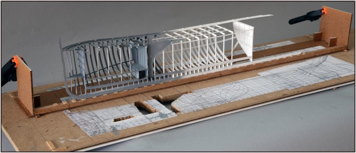
BALDER, Vlaardingen Herring Lugger from 1912, scratch build scale 1:50 Plate-On-Frame

There is a third one with colors in between. But she is a bit shy …….

That’s for sure, Uwe. She is now gonna show here lines.
Regards, Peter
Keep this (and others) in mind
 
The sheets are very thin. I have the .005”/0,13 mm or .010”/0,25 mm Evergreen sheets. My option is to rub them to provide some heat on a bit of a springy surface. Perhaps with some rolling with a steel ball. Or a hair dryer from a distance. But that will also have to be determined through trial and error.
Regards, Pete

I think that if you use styrene sheet that thin -especially the very malleable Evergreen brand - you can shape it cold for most of the hull and it will retain the shape. Cut the plates to size, lay them on top of a pad of newspaper to provide a semi-soft support and rub them with the bowl of a spoon, pressing firmly using a big spoon - not a little one - to create the concave curves you need.
 
I think that if you use styrene sheet that thin -especially the very malleable Evergreen brand - you can shape it cold for most of the hull and it will retain the shape. Cut the plates to size, lay them on top of a pad of newspaper to provide a semi-soft support and rub them with the bowl of a spoon, pressing firmly using a big spoon - not a little one - to create the concave curves you need.
Thanks for the advice, Alan. The pad of newspapers seems to be a good support for the little pressure.
From Ab Hoving I got the advice to use a piece of woodboard. And my wife has a lot of scrap-book materials.
Enough ideas to make some tests.
Regards, Peter
 
Last edited:
It's time to check if everything is still going well. That's why I've been messing around in Photoshop.
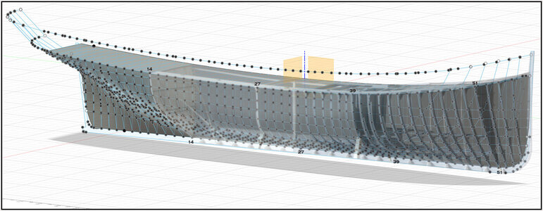
A photo of the current state placed on a print that I made at the time while drawing in Fushion 360:
It took quite a few shots before I had the model almost in the right position. Then the right lens and distance to get the perspective the same as the print at the time. This is the result of the 10th shot:
0363 Check.jpg
As 2 layers on top of each other with a transparency. The dotted lines do match very well. I can't get it completely exact. Then I have to try some other lenses and distances.
There are some differences in the curve at the bottom of the bow. But that's right. Because I couldn't get that right while drawing.
I can continue building with a clear conscience ......... :)
Regards, Peter
 
Last edited:
The side of the hull between watertight bulkheads 14 and 39 will be a lot flatter at the height of the main frame 27. Small irregularities may be extra visible there. To prevent that, I started working with the bilge stringer. Once that is in place, I can align the frames that are still to be placed on it.
I had already shown these drawings:
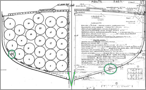
0176 Kim.jpg
On the left, where the barrels will be placed with the bilge stringer between the 5th and 6th barrel. On the right, the old technical drawing where it is in a slightly different place.

In order to be able to determine the course properly, I also placed frame 21. I now have 5 points that I can align on:
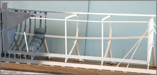
0364 Kimweger.jpg
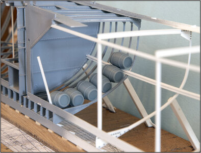
I placed a few barrels on frame 33 so that I can see that the calculated location of the bilge stringer runs between the 5th and 6th barrel.
0365 Kimweger.jpg
This is constructed from 2 L-profiles glued together.
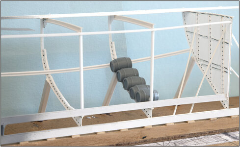
The bilge stringer runs diagonally upwards towards the rear in an arc. This is because the frames become smaller again after main frame 27 and also flatten out:
0366 Kimweger.jpg
Here are the barrels on frame 21.

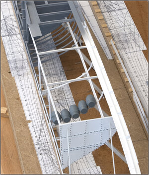
Seen from the side, it has a slightly strange course, but diagonally from above it runs almost parallel to the side of the deck:
0367 Kimweger.jpg

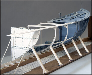
With all those curved lines, the play of lines is always different from every angle:
0368 Kimweger.jpg
And the shape of the hull is increasingly expressed by every new step.
Regards, Peter
 
It took some time to be able to show something interesting again. More or less a production line set up for the 7 frames with deck beams that are needed for the barrel hold:
0369 Tonnenruim.jpg
As mentioned before, these frames have reverse frame up to the bilge.
The frames are glued at the top with the outer deck stringer. At the bottom they are between the keel and the keelson.
They are not yet attached to the bilge stringer because I will do the final alignment when I have also placed the intermediate frames.

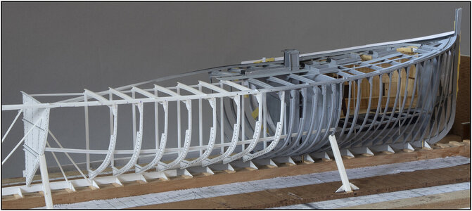
The hull shape is becoming more and more apparent:
0370 Tonnenruim.jpg
Ignore the sagging port deck stringer plate. A support has fallen away.

Due to the structure of all the beams, only 2 temporary side supports are needed:
0371 Tonnenruim.jpg
With a view of the course of all the frames.

The open starboard part:
0372 Tonnenruim.jpg
The deck beams and the longitudinal profile in the middle have enough support here from all the double U-profile styles. Where in the dressed port side part the beams come in the lengthwise direction and in the transverse direction the bulkheads between the 9 separate holds.
Now back to the production line for the 7 intermediate frames.
Regards, Peter
 
Just fantastic work, Peter! A unique and special model!
Thanks, Paul. It is also surprising to me what eventually comes about based on a few old flat drawings. It is certainly unique in terms of the use of material. In the collection of the Vlaardingen museum there should be an openwork model of the Balder, similar to my construction. However, made of brass and 2.28 meters long. Only we cannot find out where that model is.....Sick. The search continues.;)
Regards, Peter
 
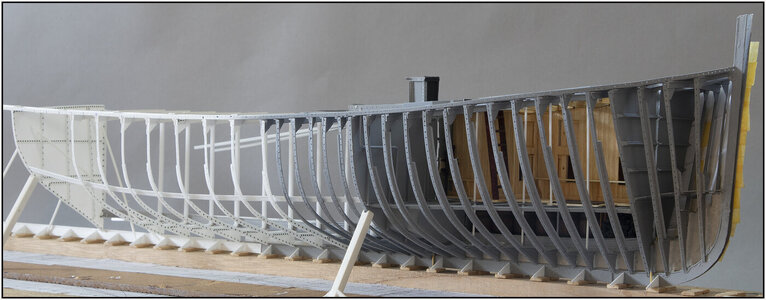
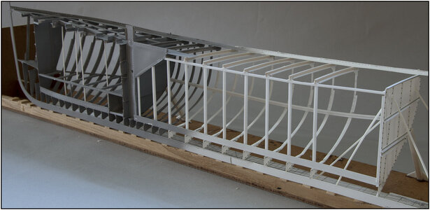
Last evening I placed the last frame of the barrel hold. But then it was too late for the photos:
0373 Tonnenruim.jpg
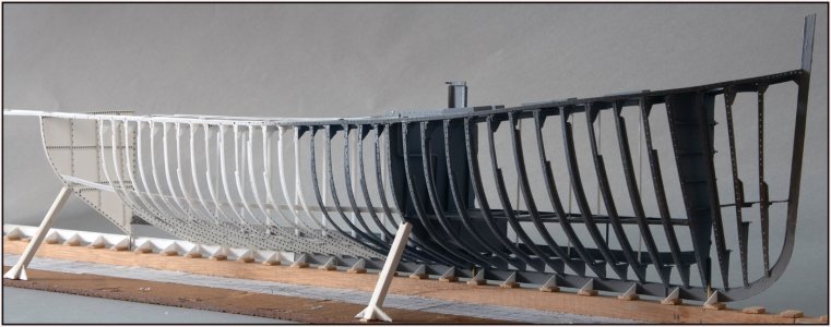
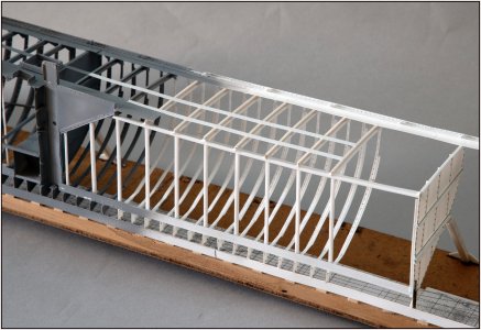
Together with the frames I had already placed at the kossing, there are 20. With the reversing frames alternately up to the bilge and up to the knee at the deck.

In itself a bit of a monotonous job, frame after frame after frame ..... But still fascinating, each frame has its own shape and size that together form the course of the hull:
0374 Tonnenruim.jpg
The open space up to bulkhead 14 is for the net hold. That has its own hatch and a different placement of the deck beams. The rivets will still be placed on the knees under the deck and other connections. But I will do that in one go when I have also closed the net hold.

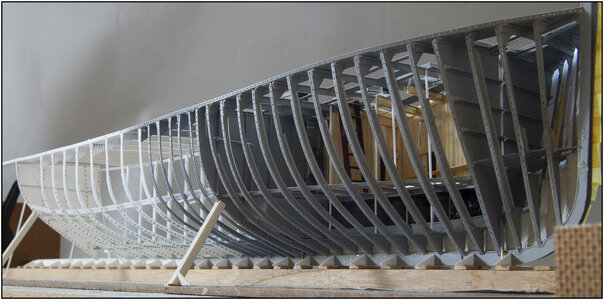
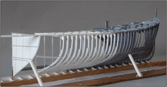
The cross-sectional plane on the inside is still flat thanks to my construction method:
0375 Tonnenruim.jpg
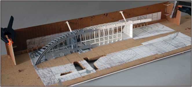
Here the construction template is tilted on the construction plate.

And put upright:
0376 Tonnenruim.jpg
The stringer plates were also placed over the deck beams, on which the sidebeams (schaarstokken) for the hatches will come later:
0377 Tonnenruim.jpg
The sheer also remains neatly present. Also on this side a lot of riveting to do.
Regards, Peter
 
Last edited:
Luckily you don't have to use the original process and equipment to install the rivets, otherwise people may start complaining.
I think my neighbors would have been at the door long ago asking me to do the work elsewhere.;) For sure the riveting gives a lot of noise.
And as always a pleasure to watch your Balder taking shape.
Thanks, Johan. A bit like the Bluenose building op frame by frame ....
Regards, Peter
 
Back
Top