What I was really curious about from the start of this build: will the frames give the skin plates a nicely flow over the frames? Was my drawing in Fushion correct and have I made the frames correct?
That is why I have already started making some test molds.
Some starting points based on the old drawings:
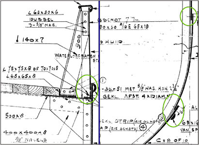
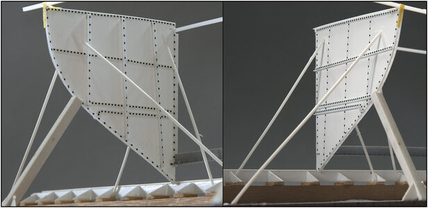
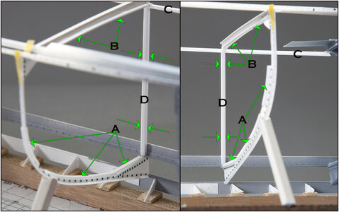
Oval left drawing: the top of the top plate protrudes a bit above the standing flange of the outer corner profile of the deck. The bulwark plate falls within the top edge of that plate and comes to rest on the standing flange.
Oval right drawing: the 2nd plate is placed over the bottom of the 1st plate and riveted. The same with the 3rd, which falls over the bottom of the 2nd plate. They worked with the plating from top till bottom.
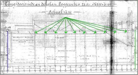
In the book of the Vlaardingen restoration there is this drawing with the 'projected' skin plan:
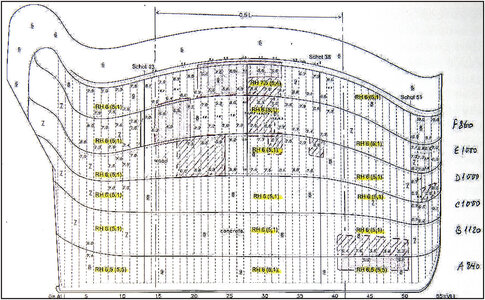
(Source: Restoration book SZB, page 21: "Skin plan VL.92".)
The proportions are clearly not correct. Therefore, in Photoshop, the drawing was shrunk in height and stretched in length:

The height was checked by making the dimensions in the blue accentuated part over the watertight bulkhead 39 in the correct size as the 39 of my model.
The first templates were made. The shape from the skin plan was not fully correct, so I had to fit, measure, cut and paste it myself:
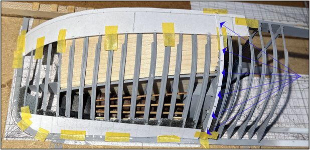
The blue arrows point to the dimensions mold on my 39 from the projected drawing of the skin plan.
Worked down strip by strip:
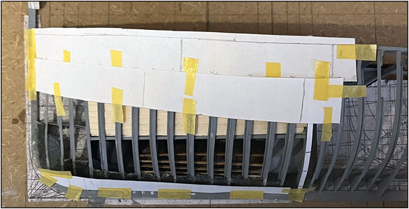
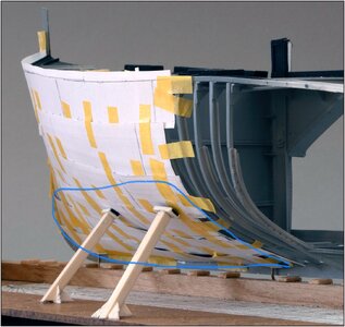
With this as a result:
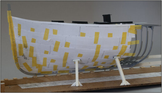
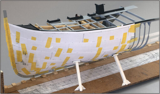
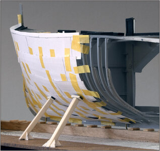
That is starting to look quite a bit like a hull shape. It is a starting point for making the final shapes. And I have to 'force' all the plates into the vertical curve. Which didn't work very well with these paper versions.
Then I have to make the edges of the individual templates a bit smoother and continue to the main frame.
But it is a start ……. And the shape of the frames is correct …..
Regards, Peter
That is why I have already started making some test molds.
Some starting points based on the old drawings:

Oval left drawing: the top of the top plate protrudes a bit above the standing flange of the outer corner profile of the deck. The bulwark plate falls within the top edge of that plate and comes to rest on the standing flange.
Oval right drawing: the 2nd plate is placed over the bottom of the 1st plate and riveted. The same with the 3rd, which falls over the bottom of the 2nd plate. They worked with the plating from top till bottom.
In the book of the Vlaardingen restoration there is this drawing with the 'projected' skin plan:

(Source: Restoration book SZB, page 21: "Skin plan VL.92".)
The proportions are clearly not correct. Therefore, in Photoshop, the drawing was shrunk in height and stretched in length:

The height was checked by making the dimensions in the blue accentuated part over the watertight bulkhead 39 in the correct size as the 39 of my model.
The first templates were made. The shape from the skin plan was not fully correct, so I had to fit, measure, cut and paste it myself:

The blue arrows point to the dimensions mold on my 39 from the projected drawing of the skin plan.
Worked down strip by strip:

With this as a result:


That is starting to look quite a bit like a hull shape. It is a starting point for making the final shapes. And I have to 'force' all the plates into the vertical curve. Which didn't work very well with these paper versions.
Then I have to make the edges of the individual templates a bit smoother and continue to the main frame.
But it is a start ……. And the shape of the frames is correct …..
Regards, Peter
Last edited:


