Belle Poule 1780 by Donnie

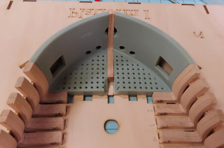
This is the latest. I have some information that Zoltan shared with me. All of the Frames have a protrusion that fits into a square opening FOR EACH FRAME. Of which are used mainly for alignment purposes. When the Frame sits down on the jig with the Peg correctly, the BACKSIDE ARCH of the Frame should make contact
with the upper part of the Jig (teeth). If that DOES NOT happen, the best remedy is to slightly FILE the square opening. But file only the LENGTH of the square and not the WIDTH of the square. This little extra notching out the open peg will allow the Frame to slide back correctly so that the backside of the arch of the frame will sit into the teeth of the jig. So, far, there have only been about 10 frames that the opening had to be increased. If the opening is not increased then the frame will NOT go back far enough into the teeth of the jig. I hope that I explained this well enough. ONLY FILE ABOUT .5 to 1mm is all is needed. Do not over-file them.

widen-holes.jpg


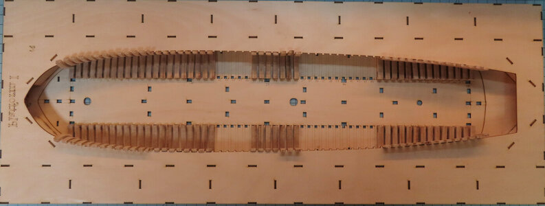
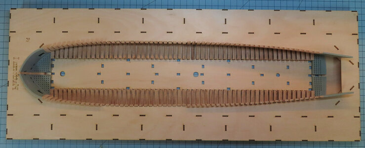
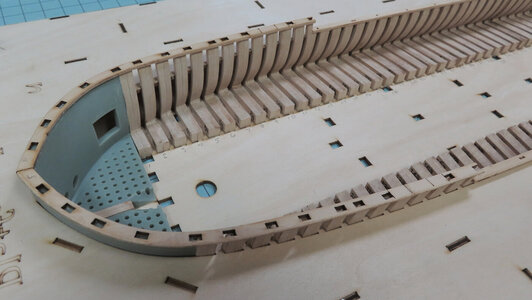
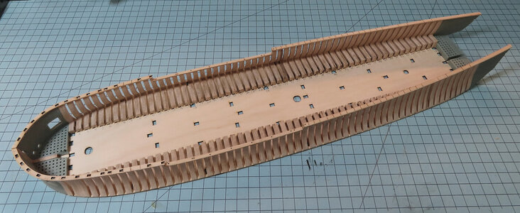
And this is the latest full view.

frames-random01.jpg
 
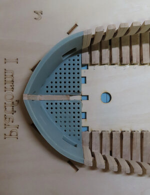
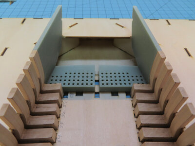
SUGGESTION: My suggestion is NOT to install Frame #1 on both sides as this will allow the installation (positioning) of the Plastic Bow piece much easier.

Thank you all for the nice compliments. I am now gluing up the plastic Bow pieces. I decided to use 2 part epoxy. The reason is that we all know that plastic is non-porous and that has to glue to wood. Then the main reason is that the epoxy gives me time to adjust the part before it cures - not like using CA. I wanted to make sure I have the part in the right place. I think CA would dry too fast.

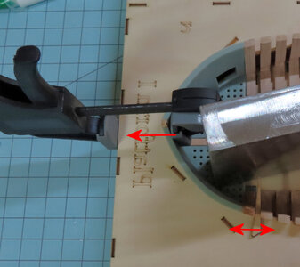
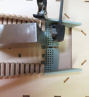
The clamp on the left is to PULL the plastic part INTO the stern post. The wooden WEDGE on the right is to PUSH Frame #1 INTO the plastic part to make tight and flush. We will see when I remove the clamps and the jig at some point as to how well I did.

stern-piece01.jpg
 
Last edited:
Thank you all for the likes - it is much appreciated.

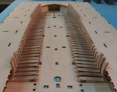
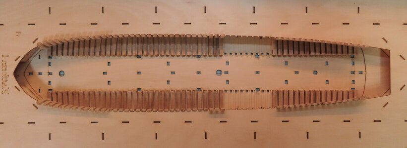
For what it is worth, I am finished with the first round of frames. Next is the installation of the (filler frames) that go in between certain frames. However, I find that the instructions call for the upper rails to be installed next. @zoly99sask did not follow this but waited. He (Zoltan) installed all the (filler frames) and waited later. This seems the most logical. However, I am wondering why 'Sail & Sail' calls for this step now. Not sure. But that is beside the point now.
Therefore, here are the latest pics.

full-view-07.jpg

full-view-05.jpg

full-view-06.jpg
 
Good evening Donni, I have no experience regarding the Kits, I am observing with some amazement the manual skills and cleanliness
 
Thank you all again for the encouragement.

So, I decided to go onto a different method than Zoltan and I decided to install the Rails per instructions. The main reason is that I think the Rails are going to add stability to the Frames when I start to fashion the Cannon ports. This might not make that much difference, but we will see. At least this method offers an alternative for those that wish to follow this method of adding the rails now instead of later.
The manual will show you a picture of a typical cross-section of how the Rails are to be positioned. Some are Flush with the Frames while (for instance), the Rails at the bow section ("X") are pretty much centered. They do tell you that the offset measuring the INSIDE of the Rail is 1mm for the "X" Rails. However, I figured out that essentially, the Rails are CENTERED for the "X" rails. The "Y" rails which are in the middle are Flush with the INSIDE Frames.
The Planking strip that installs next to these Rails is also going to have the "Decoration plate" treatment and therefore the rails and upper planking will have a few laters of decorative fashions (or moldings). This will not occur until much later in the build. I have not installed the "Z" rails yet.


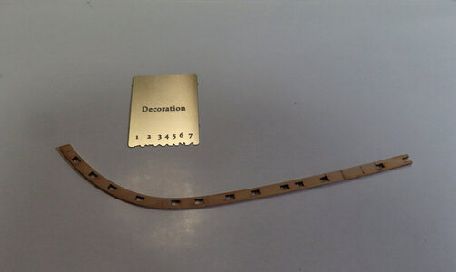
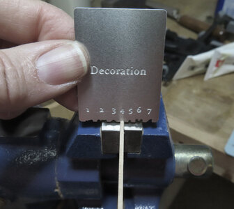
1. So, in this first picture, the kit offers a very nice 'Decoration' former that is really strong and thicker than I would have thought and seems to be made out of Stainless Steel. It is not flimsy at all, but very strong. You are supposed to use "#4" for this work on the Rails.

rails01.jpg

rails02.jpg


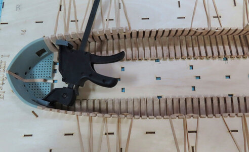
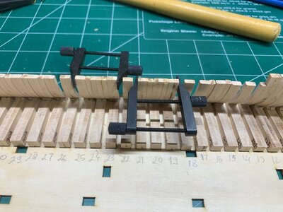
2. Next, I secured the Frame "tips" in the jig with rubber bands to make sure the frames were snug against the jig and do not move. The Rails need to have the Frames solid up against the jig and secured for rails to glue on. The clamp is reversed so to push "out" against the frames so the Bow will be secured tight up against the jig so it will not move either.

rails03.jpg


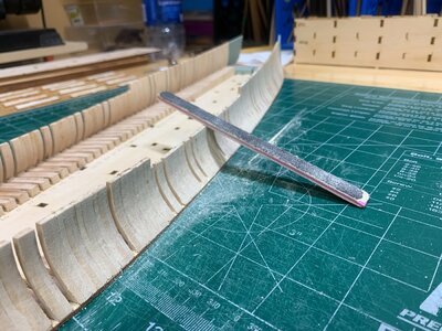
3. These Rails are in the manual are called "X", "Y" and "Z". So far just the X and Y are installed at the moment. When the Rails are installed, then the frame component will be released from the Jig.

rails04.jpg

rails05.jpg
 
Last edited:
Thank you all again for the encouragement.

So, I decided to go onto a different method than Zoltan and I decided to install the Rails per instructions. The main reason is that I think the Rails are going to add stability to the Frames when I start to fashion the Cannon ports. This might not make that much difference, but we will see. At least this method offers an alternative for those that wish to follow this method of adding the rails now instead of later.
The manual will show you a picture of a typical cross-section of how the Rails are to be positioned. Some are Flush with the Frames while (for instance), the Rails at the bow section ("X") are pretty much centered. They do tell you that the offset measuring the INSIDE of the Rail is 1mm for the "X" Rails. However, I figured out that essentially, the Rails are CENTERED for the "X" rails. The "Y" rails which are in the middle are Flush with the INSIDE Frames.
The Planking strip that installs next to these Rails is also going to have the "Decoration plate" treatment and therefore the rails and upper planking will have a few laters of decorative fashions (or moldings). This will not occur until much later in the build. I have not installed the "Z" rails yet.


1. So, in this first picture, the kit offers a very nice 'Decoration' former that is really strong and thicker than I would have thought and seems to be made out of Stainless Steel. It is not flimsy at all, but very strong. You are supposed to use "#4" for this work on the Rails.


2. Next, I secured the Frame "tips" in the jig with rubber bands to make sure the frames were snug against the jig and do not move. The Rails need to have the Frames solid up against the jig and secured for rails to glue on. The clamp is reversed so to push "out" against the frames so the Bow will be secured tight up against the jig so it will not move either.


3. These Rails are in the manual are called "X", "Y" and "Z". So far just the X and Y are installed at the moment. When the Rails are installed, then the frame component will be released from the Jig.

Hallo Donnie,
before fixing the top of the rail I would first add the fiulling elements between the frames! I think the sanding of the outer and inner "hull" etc will by much easier without the rail heads

I am just using Zoly´s photos to show this working step
FE6221F4-D9E9-4CAE-922C-23395BF0271B.jpeg E82E6BF1-CCA2-4553-A77D-28E191B6393F.jpeg
 
Hi @Uwek ,
yes, I realize that and thought about building as Zoltan. But, I wish to differ as I want to make sure my Frames are tight against the jig. I agree that it might be a little struggle to fit the extra frames, but this evening I will see the outcome.

@Kurt Konrath the decoration "blade" is very nice to work with. It takes several light passes to accomplish the mold.
 
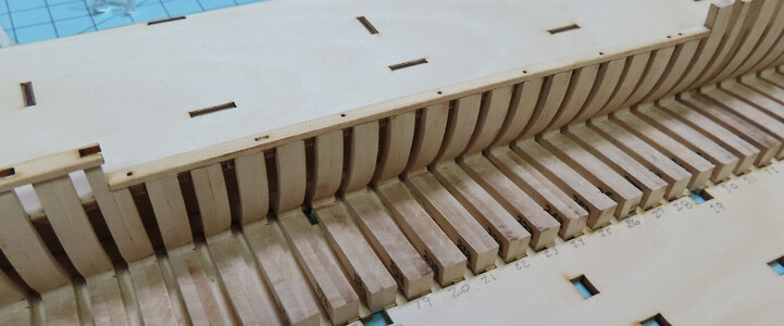
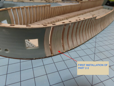
Here is the latest. Cutting the Jig away from the upper frame section. Then I made a test effort of installing one of the first of many frame "inserts". Zoltan chose a nice method of installing his frame inserts BEFORE his upper railing. However, after studying my situation, I decided to install the railings and then install the inserts.

The process was rather simple and straight forward with a little sanding on the "sides" until I could get a snug fit. About the time I sanded the tips of both ends, it seemed to fit nicely. Then I glued it up. I did not use any clamps as the piece was snug without clamps. However, this method might not be best for you, but it seems to work fine so far as I continue to install the inserts, I will see how it goes.

final-frame01.jpg


part-2-3.jpg
 
I’ve been inserting mine without the railing installed. We’re at the same stage on this build Donnie. I been swamped at work and have been feeling a bit under the weather but I’ll get back to posting in my log. Your photos are amazing by the way!
 
Reg, you must be a fast builder. It has taken me two month exactly to get to this point. I work on mine as I have the opportunity and the mood hits me. I assume that you might be retired or still employed. Hope you not offended by the question.
 
Reg, you must be a fast builder. It has taken me two month exactly to get to this point. I work on mine as I have the opportunity and the mood hits me. I assume that you might be retired or still employed. Hope you not offended by the question.

Hi Donnie :)

Don't be silly, no offense taken. I am not retired with no intention of retiring in sight, even after 42 years of working as a real estate broker. At 62, I am still full of energy so my days tend to be long in duration. When I do get a chance to build, I go at it with a vengeance however. :)
 
A continuation and latest:
Since I am not fond of a lot of sanding to make a part fit plus the fact that the part needs to be very flat, I resorted to my Mill. The reason is that the board that the "filler frames" come from is about 3.10 mm thick. The openings between the mainframes are all about 2.73 +/- about .02 mm or so.
Therefore, that leaves about .3mm of waste that has to come off for the "filler frames" will fit snuggly and also FLAT. Since this is the case, a lot of manual sanding has to be done, and to keep it flat is quite a laborious task.

The fix is to go over to the Mill and mount the stock on a piece of aluminum stock and use thin double-sided tape to hold the part down.

Disclaimer: Please do not try this unless you are comfortable with your Mill and you know what its limitations are.
Thin Double-sided tape is used and only the stickiness of the tape is holding the piece down + only small passes of .10mm are made in order NOT to put a load on the piece. Too much cut you will run the risk of the part coming off the mount. I made two passes of .10 mm and then a pass of .05mm and then I remove the part to check for fit. Most of the time, I only have to brush the sides with sandpaper just a hair to make the part somewhat snug. The white glue makes the part just slippery enough to pass the part in between the stationary frames and the upper rail which has been glued in place.

The reason I like this method is that I do not have to use clamps at all in the process.

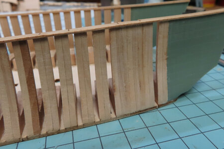
The picture below shows the final product of just slipping the "filler frame" in and a very light buff of sanding and nearly almost no sanding is really needed until I do an overall sanding.

part-57-58.jpg


This is a video showing one pass at .10 mm (Z-axis of the Mill adjusted for .10 mm)
As a side note: When the part is mounted, I will run the mill and very slowly lower the Z-axis (downward motion) until I can hear wood being shaved slightly. You can hear when the End Mill starts to make contact. I then "ZERO" the Digital Read Out - stop the Mill and then back the Mill off to "clear" the part. Then I lower the Z-axis to .10mm and then start the Mill running and then make the pass slowly. I hope this helps if someone wishes to do it this way. I used 3M Permanent Double-Sided Tape - and DO NOT REUSE. Once you trim off the part, use a NEW PIECE. Once the wood has made contact with the tape it will NOT adhere well again and you will risk the part flying off mount !!!

 
Last edited:
Back
Top