I have spent the past three weeks reading the build log of the Alfred by Dave Stevens and the Bellona build log by SJSoane of Model Ship World. I have not completed Soane's log and will re-read it when I get to p. 80. So, so much to learn. I'm probably the last person on this site to realize this but my quest for shapes of the "odd numbered" frames was a bit misguided. I now realize that the folks doing the lofting were able to create the the needed shapes from the ship's draught.
-

Win a Free Custom Engraved Brass Coin!!!
As a way to introduce our brass coins to the community, we will raffle off a free coin during the month of August. Follow link ABOVE for instructions for entering.
-

PRE-ORDER SHIPS IN SCALE TODAY!
The beloved Ships in Scale Magazine is back and charting a new course for 2026!
Discover new skills, new techniques, and new inspirations in every issue.
NOTE THAT OUR FIRST ISSUE WILL BE JAN/FEB 2026
You are using an out of date browser. It may not display this or other websites correctly.
You should upgrade or use an alternative browser.
You should upgrade or use an alternative browser.
I am going to offer an explanation and then suspend activity on this build. I have been using computer design since 1965 (IBM 360, Fortran). As recently as 2000 I used AutoCad Lt. to trace plans for a Waco YMF-5. My point is that I am somewhat conversant with CAD. I have been tracing the Bellona draught using FreeCAD. I have been looking at my work and am quite disappointed with the programs abilities. I tried adding construction lines and find that the tool is broken. I have found that the user community is a bit rude and the user manual is incomplete at best. So, Off to find an old computer on which to mount AutoCad Lt. I then need to figure out how much of my work I can salvage from FreeCAD. Rather than a build log, this has turned into a software struggle.
With that, I'm signing off for the moment.
All the best
Warren
With that, I'm signing off for the moment.
All the best
Warren
If you have not already read it, you might get some insight from Wayne Kempson's treatise on lofting. He uses Turbocad so I have no idea how well it matches with the programs you wish to use.
Allan
Allan
- Joined
- Oct 23, 2018
- Messages
- 886
- Points
- 403

If you want to work in 3D you should give Rhino a try. For 2D QCad is a really nice and also cheap alternative.
I have a question for the group. I have no desire to loft Bellona in 3D. I am simply trying to go through the exercise of lofting the lines in an effort to verify the accuracy of the Greenwich Museum drawings. I have been able to move my "FreeCAD" tracings over to LibreCAD. I have struggled to follow the steps outlined by Wayne Kempson. Realizing that Kempson fails to underscore the importance of attaching the station line identification (sheer plan) as well as the curve identification in the body plan. I backtracked a bit, ID'd the various curves and tried again. I can now follow his steps but the results are not useful. That aside, the tracing issues I mentioned for FreeCAD have come back to haunt me. It's spline tool will not allow me to faithfully follow a curve, let alone correcting errors. This means I cannot correct errors in my lofting.
Before I start all over, trying to do this in LibreCAD or AutoCAD Lite I would like to know if anyone out there has had success with any of the budget CAD programs.
Before I start all over, trying to do this in LibreCAD or AutoCAD Lite I would like to know if anyone out there has had success with any of the budget CAD programs.
I am no expert at CAD but struggle through. It is my understanding that the body plan lines and thus the frames are a series of arcs. (My memory may have failed me on this, but it does ring a bell) In any case I have always used segments of arcs to trace over the body plan station lines. If that is the case, is there any need to use the spline tool?It's spline tool will not allow me to faithfully follow a curve
Allan
- Joined
- Oct 23, 2018
- Messages
- 886
- Points
- 403

I bougth QCad Professional to do the job with my new Mac. It has all the functionality which you need to make your own drawings. I don't do the tracing of the station lines, because I find it much easier to make this part of the reconstruction with arcs and straight lines. Have a look In my signature. There you will find two examples.
My drawings are based on the original drawings of the NMM
My drawings are based on the original drawings of the NMM
Thank you both. Christian, I downloaded QCad (free version) and am proceeding with attempt 4 to loft Bellona. Scaling and moving tools are wonderful. It opens splines as polylines so I was able to tweak the really bad tracings.
Here it is one third of Feb. gone. I just completed my lofting endeavor. I used 10 water lines and all of the plan view profiles. I'm happy with the results. My criteria was simply 10 continuous curves in the new half breadth plan. I ended up using libreCAD. FreeCAD. QCAD and libreCAD provide different results when trying to connect the dots to create a half breadth curve. LibreCAD seems to have the best spline tool but its polyline tool had me concerned. As I connected the dots the lines would "oscillate." As much as I tried I could find no issues in the curves I was working from. I finally ignored the "oscillations" and finished 1/2 of one curve. I mirrored it to the right side of the drawing, ignored said oscillations and went ahead with a spline through points tool. The spline tool created what I am calling an acceptable curve.
Next, time to create frame drawings.
Next, time to create frame drawings.
Well, it looks like I spoke too soon, again. I sat down last night to re-read Kempson's "Drafting Ship Plans in CAD, A Basic Introduction." Much to my chagrin, I ain't done. He wants me to regenerate the buttock lines, replace all of the station lines on the profile plan and then regenerate the body plan. I can see the reasoning but based upon what is behind me, this is going to take a while. I suggest you not wait up.
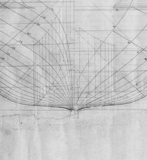
Can anyone explain what I am looking at in this attachment. I realize that the keel rabbit at the stem would be rising hence the multiple rabbit indications. I only see one for the stern but cannot fathom how far so many of the station lines cut into the keel / dead wood. 
Stations 20 through 30 sit in the dead wood and are set quite a bit above the keel yet they are shown sitting on it. I understand that the partial frames are set into the dead wood but it seems like with both sides set in there isn't going to be much holding this area together. What am I missing?

Stations 20 through 30 sit in the dead wood and are set quite a bit above the keel yet they are shown sitting on it. I understand that the partial frames are set into the dead wood but it seems like with both sides set in there isn't going to be much holding this area together. What am I missing?
Last edited:
I have been looking over pictures taken of the model at Greenwich. They definitely show the frames near/at the stern being set in just above the keel. I guess I have answered my own question. The frames are tapered as well as set in so as to be flush with the keel.
- Joined
- Oct 23, 2018
- Messages
- 886
- Points
- 403

On the left side you see the the body lines from midship to the stern. They give you the form of the hull. What you do not see in the body plan is the after deadwood, where the after cant frames are installed.
The vertical lines are construction line, which should give you a radius. This you need, if you want to reconstruct the framing with circles.
The different positions of the body plan comes not only from the from the hull design but also from the taper of the keel. From my experience I know that the stern is the most cmplex part of the whole body plan.
Have you studied any frame disposition plans? These may help explain things as well or better than words. There are quite a few on the Wiki Commons website in high resolution and the RMG Collections website in low resolution for free or in high res for a fee. I have not seen any for Bellona specifically, but the ones that can be researched might help. The plan below happens to be Vengeance (74) 1774 signed by John Williams [Surveyor of the Navy, 1765-1784]. It should be somewhat similar to Bellona
Allan

Allan

Allan and Christian thank you
As of today, I am done faring the lines for Bellona and I will admit to having cheated to get here. All of the lines forward of the flat area and the aft lines below the wales (I will explain) presented no difficulties while following Wayne Kempson's CAD write up. The area aft of the flat area and above the wales has been an on going head ache.
When I tried to fair out the aft side of the body plan I kept getting distortions in the station lines just above the wales. To make a long story short, I was able to trace the problem to an error in generating the half breadth plan aft curves above the wales. Rather than re-generate most of the work done to date, I generated the aft body plan station lines below the wales per Kempson's directions and resorted to tracing the original plan above the wales.
I am hoping that the next steps go a bit easier.
wb
So I told myself I wasn't going to post the step by step problems anymore. Well, so much for wishful thinking.
I found that I had to go to Lavery's "Bellona" to get details of the keel, stem and stern construction as none of the drawings for sister ships have said details. I have the book so it was a simple matter of scanning the stem and stern dwgs and importing them into my LibreCAD workspace. Opps, the outline of the stem does not match the outline of the stem in the original dwgs. Hmmm. Try the stern. Much better fit but it will still require some finessing.
What to do about the stem? Being and engineer at heart, I decided to compare Lavery's stem shape to his stem details. Almost a perfect match. Lavery's draftsmen did some nice work but it is not what I would call accurate.
So much for my goal of historical accuracy. Best I can do at this point is use Lavery's work as a reference and fit similar details to my drawings. For what it is worth, Lavery does not say where he obtained the details.
So at this point: Onward!
Hi WarrenSo much for my goal of historical accurac
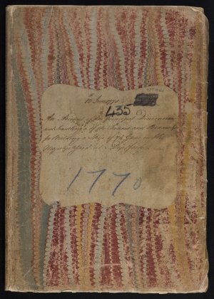
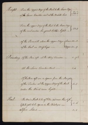
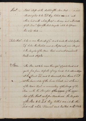
While it is for a 74 ten years after Bellona, there is an 85 page contract for Culloden (74) 1770 that is close regarding length and breadth. I think it is close enough that most, if not all, of the scantlings for her various parts should be the same or very close to that of Bellona.
Cover page and sample pages follow. If this would be interesting and helpful for you, the entire contract, dated 13 June 1770, can be found on the RMG Collections website for a free download
Allan


Thank you Allen. I found the document but it looks like I have to save all 84 images one at a time. I cannot find a means to download
Up date. Thank you again. Your suggestion had me looking at the Bombay Castle Contract. From there I went to sister ship folders (my downloads) and searched for any details of the stem and stern. For the Elephant I had a profile view that shows the major timbers of the stem. I was able to trace the major timbers, scale them an overlay on my Bellona dwings. Within tracing error, an exact fit. The drawing does not show deadwood but I understand that was built up from what was available at the ship yard.
Up date. Thank you again. Your suggestion had me looking at the Bombay Castle Contract. From there I went to sister ship folders (my downloads) and searched for any details of the stem and stern. For the Elephant I had a profile view that shows the major timbers of the stem. I was able to trace the major timbers, scale them an overlay on my Bellona dwings. Within tracing error, an exact fit. The drawing does not show deadwood but I understand that was built up from what was available at the ship yard.
Last edited:
Understood.I cannot find a means to download
Allan


