• LUCZORAMA SHIPWRECK SCAVENGER HUNT GIVEAWAY. 4 Weeks of Fun • 1 Legendary Prize ((OcCre’s Fram Ship)) • Global Crew Welcome!
    **VIEW THREAD HERE**

Bellona POF scratch build

So lets say my local printer comes back with any estimate in excess of $200.
It is over a year now, but I paid less than $1 per gun (1:64 scale), including freight. Not sure if I shared his contact information, but if not let me know via PM if you want a quote from him.
Allan
 
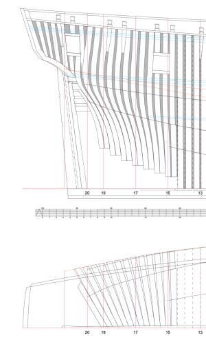
I am nearing the end of my faring effort. I am having problems with the cant frame development. I started with Lavery's drawings of both the stem and stern half breadth cant frames. I pulled them into LibreCAD and projected them onto my profile plan. I have the Bombay Castle frame disposition behind my profile plan. The projected cant frames had no relationship with what is in the Bombay Castle plan. I then turned things around. I projected the Bombay Castle cant frames onto my half breadth plan (see below). Over all, they are close except they should be straight lines. I have checked my waterline spacings and they are ok. Is it possible that the disposition drawing is not very accurate?
thank you
warren
 

Attachments

You started in the wrong direction. You have to determine the angle of each camtframe in the horizontal view. Then you can draw them in the profile view. The old time drawings are done by hand. I found for my sloop Fly out, that the profile view of Cygnet (the drawing is valid for Cygnet and all younger ships) did not match the as built drawing of Fly.
 
Hi Christian
I actually started with the half breadth (horizontal) view. I used the drawings Lavery has in his Ballona book. When Laverys drawings could not get me to the profile view I estimated the locations of the cant frames in the half breadth view and could still not get it to work. How do I estimate the horizontal locations?
I am tempted to use the drawings I attached and just trace a line from the keel to the outer most curve for each frame following the bent frames and go from there. (see attachment, red lines) I could also even out the spacing.
 

Attachments

Last edited:
Do you mean the drawings B17/1 and B17/ of the AotS Book? If there is no reproduction or drawing error this should fit. If not, you have to draw your own profile lines. Have a look in my build log for the Fly. The can't frames are the result of the given horizontal position of the cant frames you can see in the original drawing.
I estimated the locations of the cant frames in the half breadth view and could still not get it to work. How do I estimate the horizontal locations?

Easiest you can draw horizontal lines with a vertical distance of 12''. Then you can construct the position of the intersection points in the profile view.
It's a lot of work but the only possibility with a 2D cad system. That's the reason why I love smaller ships as sloops ;)
 
Christian, there is a discussion on your post #77 that was a great help. I couldn't understand where you found the cant frames in the half breadth plan. The reference to ZAZ4667 was the key. I went to the Maritime Museum and searched that document. I was surprised to see the cant frame markings. This caused me to go back the my Ballona drawings and those of her sister ships. I found similar markings on an Elephant drawing. Now to try again.
 
Warren,

be very careful to mix different sources. You get the best results, if you work only with an RMG drawing as reference. Try to implement all other details which you get from other drawings and sources in this master. (For the reconstruction of the Fly I couldn't follow this advice fully. I had to move the gun port a little bit, because it was not possible to get the position with the frame design. Perhaps the frame design for Fly changed a little bit, but there exist only the drawing of Cygnet. which I used.)
I hoped this helps you to find your way through the drawing process. I am now working more than 2 years on my drawings and I think this work will continue until I have finished the model in the far future.
 
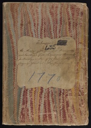
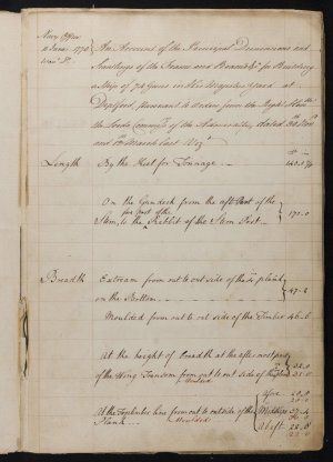
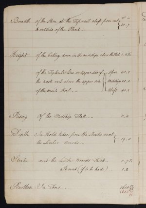
I am sure this will be little for drafting cant frames, and I am not sure this would be of any help overall as it is ten years after Bellona, but there is an 85 page contract for a 74 dated 1770. Cover page and first two pages are below. You can match the numbers to see if they are the same or very different than Bellona. If the same or close it may be useful for you with scantlings for all the parts of the floors and frames and everything else on the ship.
Allan
1750413250332.jpeg
1750413285508.jpeg
1750413331351.jpeg

There are about nine pages just describing the frames from the floors to top timbers that you may find interesting.

Allan
 
Warren,

be very careful to mix different sources. You get the best results, if you work only with an RMG drawing as reference. Try to implement all other details which you get from other drawings and sources in this master. (For the reconstruction of the Fly I couldn't follow this advice fully. I had to move the gun port a little bit, because it was not possible to get the position with the frame design. Perhaps the frame design for Fly changed a little bit, but there exist only the drawing of Cygnet. which I used.)
I hoped this helps you to find your way through the drawing process. I am now working more than 2 years on my drawings and I think this work will continue until I have finished the model in the far future.
Allan
Very good advice. Thank you
warren
 
I am sure this will be little for drafting cant frames, and I am not sure this would be of any help overall as it is ten years after Bellona, but there is an 85 page contract for a 74 dated 1770. Cover page and first two pages are below. You can match the numbers to see if they are the same or very different than Bellona. If the same or close it may be useful for you with scantlings for all the parts of the floors and frames and everything else on the ship.
Allan
View attachment 526753
View attachment 526754
View attachment 526755

There are about nine pages just describing the frames from the floors to top timbers that you may find interesting.

Allan
Allan
I have that contract. I'm not sure where I obtained it but I have it attributed to the Culloden. That contract and the Bombay Castle contract are my main source of scantlings.
warren
 
Allan and Christian
I think I need to step back again. Try as I might I have been unable to map cant frames. I even used the Elephant frame resolution plan and the marked up Elephant profile drawing. I have just ordered "Plank on Frame Models" so as to see someone else's view of this task.
Thank you for your help.
warren
 
Can anyone here offer up a ships draught that you have gone through and successfully projected the cant frames from the half breadth plan to the sheer plan and had the frames match up with the as built drawing?
In the distant past I was taught how to project pipe junctions onto the flat to facilitate making flat patterns to be used in marking the pipe for cutting.
I went through this entire lofting exercise yesterday and can see how it all works. I can easily visualize projecting a cant frame drawn on the half breadth plan to the sheer plan.

EDIT
I have located Christian's build log for Triton. Attached to that is a list of available dwgs including Sheer Plan, Frame Disposition and As built for Boreas. Boreas is the ship Wayne Kempson used in his CAD discussion. I will attempt to follow Kempson's process, line by line using the same drawings. Time will tell


warren
 
Last edited:
I did the exercise for my sloop project and send have shown the results in my build log. I do not understand in the moment where you have problems.
Can you share your horizontal lines and the profile?
 
I did the exercise for my sloop project and send have shown the results in my build log. I do not understand in the moment where you have problems.
Can you share your horizontal lines and the profile?
I have found your Triton build log. Triton is a sister ship to Boreas which is the ship (and plans) that Wayne Kempson used as an example. I am going to attempt to follow his example.
Attached is an example of the problem I am having. The projected line does not agree with the underlying cant frames.
warren
 

Attachments

If I have a look to your document, I see, that the vertical lines did not really match the intersection points of the horizontal line and the can't frame line.
To make it easier you should only draw the vertical lines until the horizontal line in the profile view. You need an extra vertical line for the breath extreme.

Which kind of splines do you use? Control points or adjustment points. I recommend to use splines with adjustment points for all horizontal and vertical lines. I do not have any problems using the same technique as you.
 
Back
Top