Dave in the kit is the JIG INCLUDED OR CAN IT BE AN ADD ON. THANKS FOR EVERYTHING Don

-

SUBSCRIBE TO SHIPS IN SCALE TODAY!
The beloved Ships in Scale Magazine is back and charting a new course for 2026!
Discover new skills, new techniques, and new inspirations in every issue.
NOTE THAT OUR NEXT ISSUE WILL BE July/August 2026 -

Win a Free Custom Engraved Brass Coin!!!
As a way to introduce our brass coins to the community, we will raffle off a free coin during the month of August. Follow link ABOVE for instructions for entering.
You are using an out of date browser. It may not display this or other websites correctly.
You should upgrade or use an alternative browser.
You should upgrade or use an alternative browser.
Bomb vessel cross section - scale 3/8 or 1:32
- Thread starter Dave Stevens (Lumberyard)
- Start date
- Watchers 16

Dave, before using your one piece keel you might want to check your frames to ensure the upper futtocks are long enough. If you simply traced them for laser cutting from the original plans its possible that they may not. I can't remember from what I did and am not home to check for you. I'm assuming of course, from your explanation that the keel will be the same thickness fore and aft. If I'm incorrect, disregard this. ")
Second thought, you might want to include the step up to ensure there is enough timber to allow for sanding on the floors of those frames.
- Joined
- Dec 1, 2016
- Messages
- 6,712
- Points
- 728

Dave, before using your one piece keel you might want to check your frames to ensure the upper futtocks are long enough. If you simply traced them for laser cutting from the original plans its possible that they may not. I can't remember from what I did and am not home to check for you. I'm assuming of course, from your explanation that the keel will be the same thickness fore and aft. If I'm incorrect, disregard this.
yes I see there is a step in the keel
as far as the thickness goes fore and aft the keel has no taper it is the same as you can see in the drawing with the red lines drawn in cad, however the height from the first frame D to frame 8 is the same but from frame 9 to frame 12 there is a step up. so yes the one keel does include this stepping.

Yes! What you said! That's what I meant.
Perhaps I should have used the term "depth of the keel fore and aft". Main point being, if you are using a flat topped keel instead of the stepped one to simplify things make sure the top futtocks were long enough on those frames that are stepped up or you may have a drop off instead. I can't remember how they were while I mounted them on the keel.
Perhaps I should have used the term "depth of the keel fore and aft". Main point being, if you are using a flat topped keel instead of the stepped one to simplify things make sure the top futtocks were long enough on those frames that are stepped up or you may have a drop off instead. I can't remember how they were while I mounted them on the keel.
- Joined
- Dec 1, 2016
- Messages
- 6,712
- Points
- 728
I have prepped up the keel as one unit as drawn on the original plan


the notches drawn on the plan is for the floor timbers of the double frames to sit down into and the second floor notches over the keel.
this is one of those details i eliminated because 1 it is never seen on the finished model 2 it just adds more time and work to the model. so this is something another builder might want to take the time to do.
- Joined
- Dec 1, 2016
- Messages
- 6,712
- Points
- 728
setting up the keel by using 2 sided tape on the bottom it was stuck to the block. i made sure the keel was at 90 degrees to the bottom of the block by using a triangle. also the keel was set in the center of the block.

also using a square i made sure the keel is sitting at a 90 degree to the block.

now that is it this is what I have.

also using a square i made sure the keel is sitting at a 90 degree to the block.
now that is it this is what I have.
- Joined
- Dec 1, 2016
- Messages
- 6,712
- Points
- 728
ready to frame up the hull
I did this method a couple different ways in the past and it seems to work out just fine. The idea is stacking the hull frames rather than jigging them and here is what I do.
I set my block with the keel on a sheet of glass to make sure everything is flat and square. I know by block is square so setting it on the glass i have a 90 degree angle between the keel and work surface

keel and frame and work surfaces are all square and flat

there is a reason for setting the keel in the center of the block. Looking down at the frame and seeing the edges of the block i can take measurements from the block to the frame on both sides. This is the one measurement that insures i have the frame sitting straight from side to side. Setting up this first frame is the critical one because it will be used as a reference to stack the next frame.


I did this method a couple different ways in the past and it seems to work out just fine. The idea is stacking the hull frames rather than jigging them and here is what I do.
I set my block with the keel on a sheet of glass to make sure everything is flat and square. I know by block is square so setting it on the glass i have a 90 degree angle between the keel and work surface
keel and frame and work surfaces are all square and flat
there is a reason for setting the keel in the center of the block. Looking down at the frame and seeing the edges of the block i can take measurements from the block to the frame on both sides. This is the one measurement that insures i have the frame sitting straight from side to side. Setting up this first frame is the critical one because it will be used as a reference to stack the next frame.
Last edited:
- Joined
- Dec 1, 2016
- Messages
- 6,712
- Points
- 728
looking at the drawings the space between the blue arrows will be covered inside and out with planking

from the waterline to the cap rail is planked over so placing spacers in this location will be covered.

i glued the spacers to the face of frame D in the location of the blue arrows and a spacer above the keel which will be hidden by the keelson.

from the waterline to the cap rail is planked over so placing spacers in this location will be covered.
i glued the spacers to the face of frame D in the location of the blue arrows and a spacer above the keel which will be hidden by the keelson.
Last edited:
- Joined
- Dec 1, 2016
- Messages
- 6,712
- Points
- 728
next comes frame C and it is glued to the face of the spacers on frame D

The way I know frame C is in the correct location and not tilted sideways is from the space between frame D and C. The hull is facing bow down so each frame added will be slightly larger than the one below it until I reach the midship frame then the frame will get narrower as I stack them.

I tinted the area I am watching blue, so I made sure the space on both sides are the same. I might be ever so slightly off by placing frame C by eye but it is so close and I will give the hull and final sanding once all the frames are in place. so slightly off does not matter all that much.
The spacers are MDF board which is a pressed board almost like a very dense cardboard so i am letting the spacer hang over the edge of the frames. Because the MDF board is softer than the Birch frames they will sand down to the frames with no problem.
The way I know frame C is in the correct location and not tilted sideways is from the space between frame D and C. The hull is facing bow down so each frame added will be slightly larger than the one below it until I reach the midship frame then the frame will get narrower as I stack them.
I tinted the area I am watching blue, so I made sure the space on both sides are the same. I might be ever so slightly off by placing frame C by eye but it is so close and I will give the hull and final sanding once all the frames are in place. so slightly off does not matter all that much.
The spacers are MDF board which is a pressed board almost like a very dense cardboard so i am letting the spacer hang over the edge of the frames. Because the MDF board is softer than the Birch frames they will sand down to the frames with no problem.
- Joined
- Dec 1, 2016
- Messages
- 6,712
- Points
- 728
to jig or not to jig depends on the builder. Building a hull in a jig is definitely the way to go. Personally I have built a number of hulls using a jig in the Hahn style where the frames are extended above the hull and fit into the jig notches. I am not a fan of placing a jig around the hull because that prevents any work on the hull until it is removed from the jig. In the case of this model being a cross section and the hull is only the mid section it made possible to stack the frames using spacers.

Gluing spacers between frames it makes the hull a solid structure the spacers are acting as the notches in the jig.

What I like about this method it frees the hull so I can view it from any angle, I can work on the hull inside and out. This completes the first section of the hull and it worked out perfectly. Everything is in line, square and straight. The MDF spacers are soft and they will grind out even with the frames with no problem.
section one went from the double frame D three filler single frames and the double midship frame. This gives me a solid foundation to stack up the next 4 frames using the midship frame as my guild.
Gluing spacers between frames it makes the hull a solid structure the spacers are acting as the notches in the jig.
What I like about this method it frees the hull so I can view it from any angle, I can work on the hull inside and out. This completes the first section of the hull and it worked out perfectly. Everything is in line, square and straight. The MDF spacers are soft and they will grind out even with the frames with no problem.
section one went from the double frame D three filler single frames and the double midship frame. This gives me a solid foundation to stack up the next 4 frames using the midship frame as my guild.

I agree, spacers help. I used them in the Blandford Cross Section and they allowed me to remove the spreaders without losing the rigidity of the hul.
Daves, Thanks for the idea, it may have solved one of my big problems in scratch building a POF build, will try it out. THANKS AGAIN FOR THIS INFORMATIVE THREAD ALWAYS LEARNING FROM YOU Don
- Joined
- Dec 1, 2016
- Messages
- 6,712
- Points
- 728
now for frames 1,2,3,4 but first I need to cut the oar ports into the side of the frames. those are the little square openings you can see in post #49 between the gun ports. This was a simple job of sawing the stop cuts and mounting the frame in the small vice and cutting the port down to the vice level.


wonderfull thread as useal. Don
- Joined
- Dec 1, 2016
- Messages
- 6,712
- Points
- 728
I agree, spacers help. I used them in the Blandford Cross Section and they allowed me to remove the spreaders without losing the rigidity of the hul.
Dave
Daves, Thanks for the idea, it may have solved one of my big problems in scratch building a POF build, will try it out. THANKS AGAIN FOR THIS INFORMATIVE THREAD ALWAYS LEARNING FROM YOU Don
thanks Dave for good information, I will also use this technique in my Blandford Cross Section project such as Doc Blake.
KNUT
thanks guys for the comments
The biggest problem when framing up a hull is keeping all the frames inline this first example is a frame that will lean forward or backward so this is the first direction you have to account for. Even if the wood you use is totally dry just changes in temperature or humidity will cause a frame to move.

even when you use spacers you can still develop a slant to the frames.

next you have to keep in mind the frame from side to side if this is not correct the hull will twist.

Frames have to be set at 90 degrees to the keel

frames have to line up with each other

building in some sort of jig or using spacers it comes down to lining up the frame in a number of directions and holding them there until the hull can be stablized. In this example the hull used spacers along the top

here the hull is built in a jig. The dark area is an extension of the frames to the jig.

Dave
Daves, Thanks for the idea, it may have solved one of my big problems in scratch building a POF build, will try it out. THANKS AGAIN FOR THIS INFORMATIVE THREAD ALWAYS LEARNING FROM YOU Don
thanks Dave for good information, I will also use this technique in my Blandford Cross Section project such as Doc Blake.
KNUT
thanks guys for the comments
The biggest problem when framing up a hull is keeping all the frames inline this first example is a frame that will lean forward or backward so this is the first direction you have to account for. Even if the wood you use is totally dry just changes in temperature or humidity will cause a frame to move.
even when you use spacers you can still develop a slant to the frames.
next you have to keep in mind the frame from side to side if this is not correct the hull will twist.
Frames have to be set at 90 degrees to the keel
frames have to line up with each other
building in some sort of jig or using spacers it comes down to lining up the frame in a number of directions and holding them there until the hull can be stablized. In this example the hull used spacers along the top
here the hull is built in a jig. The dark area is an extension of the frames to the jig.
Last edited:
Hi Dave getting desperate, trying to find guide bearings for my band saw, contacted Carter, they said they do not make the guide bearings for a 9 inch table top band saw, the blade is flutering badly have tried to retension but to no avail, SORRY FOR HIJACKING THIS THREAD. Don
- Joined
- Dec 1, 2016
- Messages
- 6,712
- Points
- 728
setting frame 3 in place I dropped it and it broke, this however gave me another idea. first I glued the bottom half in place on the stack then used a spacer bridge across the frame and set the top pieces on the spacer and fit it back into the chock. It dawned on me this might be another possible way to build this hull. Build up each frame right in place on top of the stack using the frame below it as a template.

- Joined
- Dec 1, 2016
- Messages
- 6,712
- Points
- 728
Hi Dave getting desperate, trying to find guide bearings for my band saw, contacted Carter, they said they do not make the guide bearings for a 9 inch table top band saw, the blade is flutering badly have tried to retension but to no avail, SORRY FOR HIJACKING THIS THREAD. Don
maybe cool blocks will work blade flutters because the guides are not adjusted
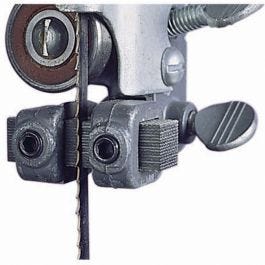
Olson® Cool Blocks® for Band Saw
Improve your band saw performance with the blade guide blocks recommended by professionals!
 www.rockler.com
what make is your saw?