Happy Birthday and may the sound of the mortars salute your day. RichHappy Birthday Doctor Dave! Hope you had a great, spoiled day!
You are using an out of date browser. It may not display this or other websites correctly.
You should upgrade or use an alternative browser.
You should upgrade or use an alternative browser.
Bomb Vessel Granado 1742 - Cross Section - 1:32 Scale - Scratch Build by DocBlake [COMPLETED BUILD]
Thanks for the birthday wishes!
It's been a busy couple of months! We're redoing the flooring in two bedrooms in the house so I had to remove carpeting and underlayment to prep for hardwood floor installations. Lots of work. Also painted the entire downstairs of the house as well as those two bedrooms. To reward ourselves, Liz and I took the family to St. Martin FWI for a well needed vacation. Our first trip back in nearly 2 years. It felt great. Now my consulting work is ramping up, keeping me busy, but I'm committed to getting back to the workbench!
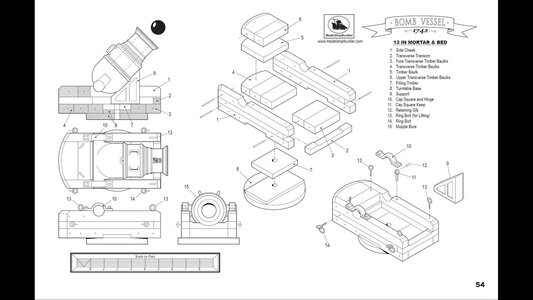
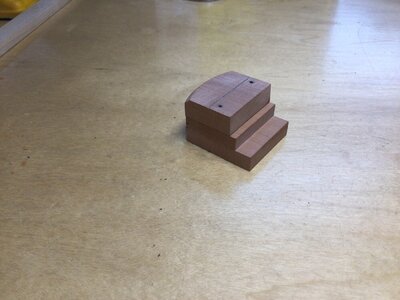
I began work on the mortar bed. To look at a finished bed, it doesn't appear too challenging. I'm coming to discover that it is the most difficult part of this build by far! There are 19 parts comprising the bed as shown on the plans, not including the iron support and the mortar itself. The first problem is dimensions. Almost of these parts are different thicknesses, but must result in a bed that is uniform in height and width. The second problem is the scale. At 1:32 the lines comprising the plan drawings have a fair amount of thickness to them. So depending on where you measure, you possibly have variation of up to 1/32" to 3/64". The layout and cutting parts is slow, tedious, precise work that took a good number of hours.
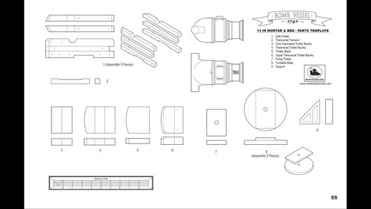
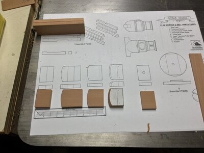
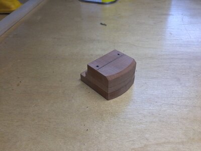
The first step was to cut out the component parts. The rear part of the bed is made of three stacked parts, all curved. The top one has a 45 degree bevel cut into it. The photos show the plans, the component parts and the three slice stacked piece with the curved, beveled surface facing the rear. The wood is swiss pear.


- Joined
- Apr 20, 2020
- Messages
- 5,146
- Points
- 738

Dear DocThanks for the birthday wishes!
It's been a busy couple of months! We're redoing the flooring in two bedrooms in the house so I had to remove carpeting and underlayment to prep for hardwood floor installations. Lots of work. Also painted the entire downstairs of the house as well as those two bedrooms. To reward ourselves, Liz and I took the family to St. Martin FWI for a well needed vacation. Our first trip back in nearly 2 years. It felt great. Now my consulting work is ramping up, keeping me busy, but I'm committed to getting back to the workbench!
I began work on the mortar bed. To look at a finished bed, it doesn't appear too challenging. I'm coming to discover that it is the most difficult part of this build by far! There are 19 parts comprising the bed as shown on the plans, not including the iron support and the mortar itself. The first problem is dimensions. Almost of these parts are different thicknesses, but must result in a bed that is uniform in height and width. The second problem is the scale. At 1:32 the lines comprising the plan drawings have a fair amount of thickness to them. So depending on where you measure, you possibly have variation of up to 1/32" to 3/64". The layout and cutting parts is slow, tedious, precise work that took a good number of hours.
The first step was to cut out the component parts. The rear part of the bed is made of three stacked parts, all curved. The top one has a 45 degree bevel cut into it. The photos show the plans, the component parts and the three slice stacked piece with the curved, beveled surface facing the rear. The wood is swiss pear.
View attachment 280124View attachment 280125View attachment 280126View attachment 280127View attachment 280128
Good luck with the home construction project, I hope that you enjoyed with your family vacation in San Martin.
Indeed the project of the mortar and its infrastructure looks Challenging, I have no doubt that you will be able to deal with it with great success
Kurt Konrath
Kurt Konrath
Glad your back in the new year, and hope you enjoyed time off with family.
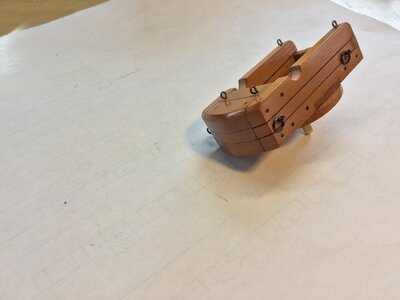
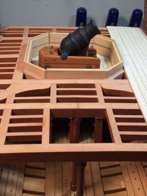
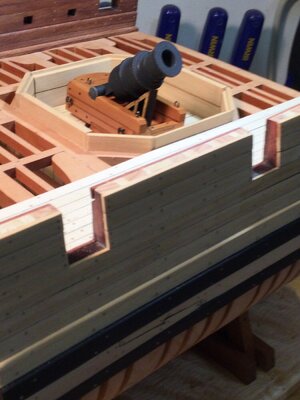
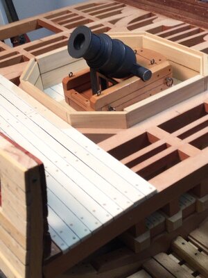
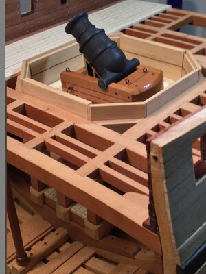
I finished up the mortar bed. It was a complex little build that took several days, but was a fun project on it's own. The varying thicknesses of wood that needed to be milled and when stacked on each other so the top of the bed was flat called for a lot of precision and caused lots of heartburn! But..it's done!
Mortar beds were originally stationary on deck, so to aim, the ship needed to move such that the mortar lined up with it's target. Not very practical. The solution was to put the bed on a revolving "lazy susan" that sits in the recess in the mortar pit. The rotation was around an iron spindle, shown in the photos as a 5/32" brass rod. This allowed greater ease of aiming, but made it necessary to pay attention so one didn't shoot the masts, yards and rigging of one's own ship!
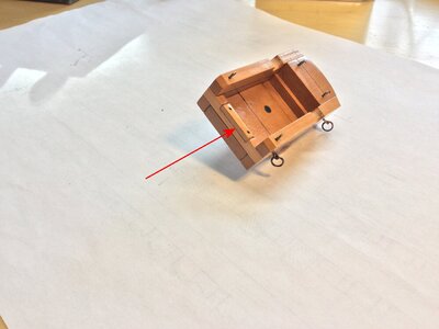
When not in use, the mortar was lowered into the horizontal position resting on the transom, and the entire bed was rotated so the mortar was aligned with the long axis of the ship. Because of the wear and tear the mortar barrel would cause resting on the top of the transom, I added a sacrificial transom board to the top that could be replaced if needed. Sort of like billboards for the anchors. The red arrow points this out.
The mortar is 3D printed. I'll be using a cast mortar for the model.
Next up is the mortar housing.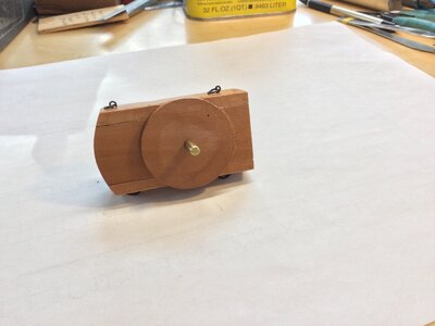


Last edited:
Kurt Konrath
Kurt Konrath
That almost looks like a black frog squatting on the deck.
An additional perspective for your excellent work, coming from my younger brother and his historical naval warfare revelation to me, was that if the mortar ship could come up tight under the larger warship, whose guns could not be depressed sufficiently, the mortar could be used to demolish the spars and rigging of the warship. This comes to mind when I see the mortar muzzle upwards. You have an outstanding work being produced. Rich (PT-2)I finished up the mortar bed. It was a complex little build that took several days, but was a fun project on it's own. The varying thicknesses of wood that needed to be milled and when stacked on each other so the top of the bed was flat called for a lot of precision and caused lots of heartburn! But..it's done!
Mortar beds were originally stationary on deck, so to aim, the ship needed to move such that the mortar lined up with it's target. Not very practical. The solution was to put the bed on a revolving "lazy susan" that sits in the recess in the mortar pit. The rotation was around an iron spindle, shown in the photos as a 5/32" brass rod. This allowed greater ease of aiming, but made it necessary to pay attention so one didn't shoot the masts, yards and rigging of one's own ship!
When not in use, the mortar was lowered into the horizontal position resting on the transom, and the entire bed was rotated so the mortar was aligned with the long axis of the ship. Because of the wear and tear the mortar barrel would cause resting on the top of the transom, I added a sacrificial transom board to the top that could be replaced if needed. Sort of like billboards for the anchors. The red arrow points this out.
The mortar is 3D printed. I'll be using a cast mortar for the model.
Next up is the mortar housing.View attachment 280614View attachment 280615View attachment 280616View attachment 280617View attachment 280618View attachment 280619View attachment 280627
Clean perfect joinery wow. I’m taking lessons
But that frog can really CROAK! RIchThat almost looks like a black frog squatting on the deck.
Great work on the mortar - very good work definitely
Thanks, guys!
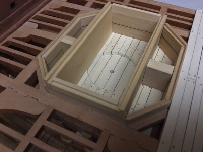
I have been spending some time building the removable pit housing for the mortar pit. This was a removable structure that protected the mortar from the weather when not in use and also provided protected storage space. As I worked, I realized that the housing would obscure too much detail on the mortar and bed, so I decided to stop construction and move on to something else.
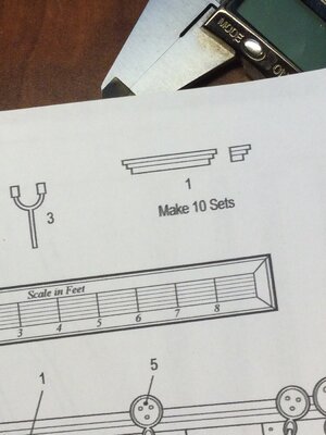
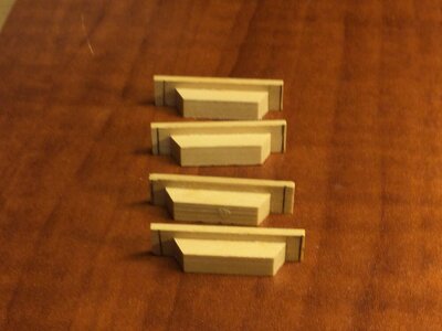
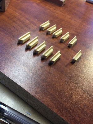
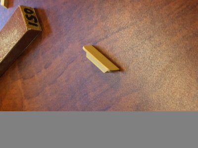
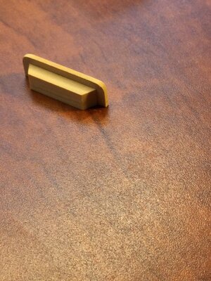
The boarding steps in Jeff Staudt's plans are cut from a single piece of wood, and I didn't really care much for the design, so I used my own design!
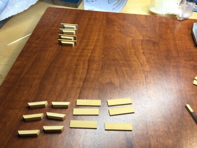
The treads are 3/64" thick boxwood and the risers are 7/64" boxwood. The ends of the risers are cut at a 60 degree angle and the tread overhangs the riser on three sides. Rather than try to glue the treads to the risers and get the overhangs perfect, I left the treads oversized when I glued up each step. I then marked them to the proper length and "cut" them to size using the disk sander. Rounding the tread corners finished the job. There are 5 steps per side.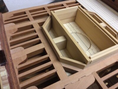


Kurt Konrath
Kurt Konrath
Now you have shown us you can step up to any task needed for this build. 
Your log and precise craftsmanship are a stimulating voyage to follow for what is possible to emulate. Your build is never disappointing. RichThanks, guys!
I have been spending some time building the removable pit housing for the mortar pit. This was a removable structure that protected the mortar from the weather when not in use and also provided protected storage space. As I worked, I realized that the housing would obscure too much detail on the mortar and bed, so I decided to stop construction and move on to something else.
The boarding steps in Jeff Staudt's plans are cut from a single piece of wood, and I didn't really care much for the design, so I used my own design!
The treads are 3/64" thick boxwood and the risers are 7/64" boxwood. The ends of the risers are cut at a 60 degree angle and the tread overhangs the riser on three sides. Rather than try to glue the treads to the risers and get the overhangs perfect, I left the treads oversized when I glued up each step. I then marked them to the proper length and "cut" them to size using the disk sander. Rounding the tread corners finished the job. There are 5 steps per side.View attachment 283580View attachment 283581View attachment 283582View attachment 283586View attachment 283587View attachment 283588View attachment 283589View attachment 283590
awsome. you have set the bar to high for me.
Very good work my friend - Bravo
Interesting that in striving to attain high bars, we are not exposed to strained muscle injuries or broken bones as with athletes of younger years.Very good work my friend - Bravo
Rich (PT-2)
Thanks, guys!
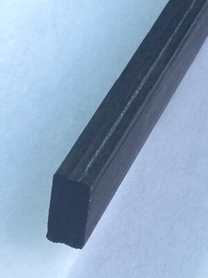
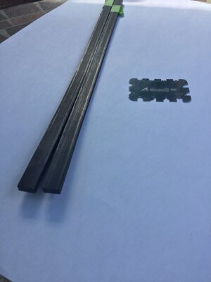
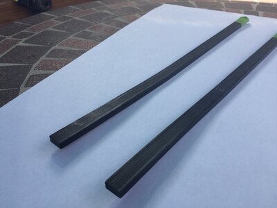
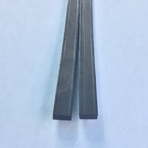
Next up are the main rails. These are made of ebony, 7/16" wide and7/32" thick. I started by cutting out the blanks a bit long. Then I plowed a decorative rabbet into the inboard and outboard edges of each rail using an Artesania Latina scraper.
The rails rise, moving aft, over the last 8 frames, and there is a distinct narrowing of the hull over the last 4 frames. That means the rails must be curved upward quite a bit as well as edge-bent inwardly. Using ebony, this wasn't easy!
I used a Milwaukee brand heat gun to do the compound bend it two steps. This is really a hit-or-miss proposition as it's difficult to "undo" a mistake after the wood is bent. Have extra rail blanks! I got lucky and both rails bent correctly the first time. The photos show the rail blanks after bending.


 wishing you all the best and happiness

