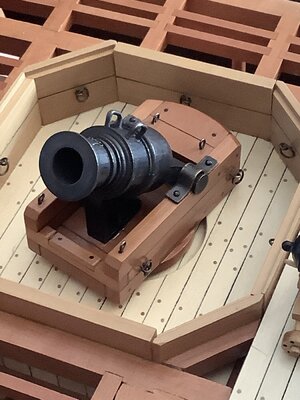
You are correct - I mixed it up with the "ling nine" used as a chaser with a longer barrel at the bow - and the Granado nevere chased another shipHi Uwe. This 4 pounder is, in fact, a “long gun”, to differentiate these carriage mounted cannons from swivel guns and carronades!
-

Win a Free Custom Engraved Brass Coin!!!
As a way to introduce our brass coins to the community, we will raffle off a free coin during the month of August. Follow link ABOVE for instructions for entering.
-

PRE-ORDER SHIPS IN SCALE TODAY!
The beloved Ships in Scale Magazine is back and charting a new course for 2026!
Discover new skills, new techniques, and new inspirations in every issue.
NOTE THAT OUR FIRST ISSUE WILL BE JAN/FEB 2026
You are using an out of date browser. It may not display this or other websites correctly.
You should upgrade or use an alternative browser.
You should upgrade or use an alternative browser.
Bomb Vessel Granado 1742 - Cross Section - 1:32 Scale - Scratch Build by DocBlake [COMPLETED BUILD]
You are right about Granado never chasing another ship! LOL!You are correct - I mixed it up with the "ling nine" used as a chaser with a longer barrel at the bow - and the Granado nevere chased another ship
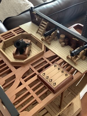
I finished up the main hatch by adding the eyebolts and rings to the covering boards. Both are made of .032" diameter brass rod, blackened with Brass Black.
The eyebolts are made with a jewelry making tool known as a "looper". The rings are annealed brass rod, using a torch, which is blackened, then wrapped around an appropriate sized drill bit and cut free with a wire cutter.
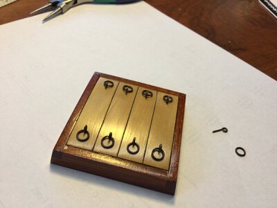
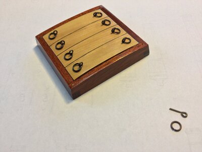
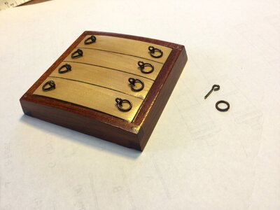
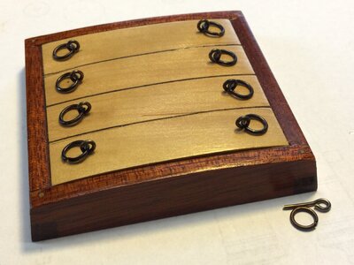
The eyebolts are made with a jewelry making tool known as a "looper". The rings are annealed brass rod, using a torch, which is blackened, then wrapped around an appropriate sized drill bit and cut free with a wire cutter.


Looks absolutely great.
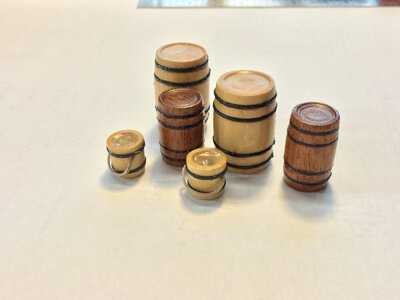
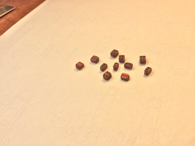
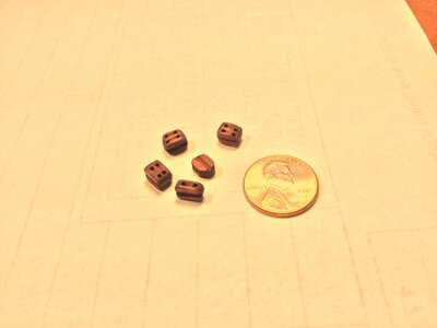
Single and double blocks made from scratch. The wood is swiss pear finished with boiled linseed oil. The single blocks are 1/4" long (8" in scale) and 3/16" wide with a 1/8" thickness. The double blocks are 1/4" long, 3/16" wide and 3/16" thick. The sheave holes are drilled with a #60 drill to accommodate .025" diameter gun tackle line. The penny gives size perspective.


- Joined
- Apr 20, 2020
- Messages
- 6,257
- Points
- 738

your Single and double blocks, looks very nice, well done my friendSingle and double blocks made from scratch. The wood is swiss pear finished with boiled linseed oil. The single blocks are 1/4" long (8" in scale) and 3/16" wide with a 1/8" thickness. The double blocks are 1/4" long, 3/16" wide and 3/16" thick. The sheave holes are drilled with a #60 drill to accommodate .025" diameter gun tackle line. The penny gives size perspective.
View attachment 347052View attachment 347053


Looking great Doc.
- Joined
- Sep 14, 2020
- Messages
- 152
- Points
- 88

Well done, its a beauty. Can't hardly wait for the final picture. Are you going to case this model?
I am planning on casing the model!
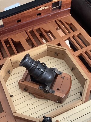
Does anyone have any information on how the mortar was rigged?
There is nothing in Jeff's plans and nothing in Goodwin's book to guide the rigging. Obviously it involved block and tackle attached to the mortar bed and the walls of the mortar pit, but how many, and where were they placed?
Dave
Does anyone have any information on how the mortar was rigged?
There is nothing in Jeff's plans and nothing in Goodwin's book to guide the rigging. Obviously it involved block and tackle attached to the mortar bed and the walls of the mortar pit, but how many, and where were they placed?
Dave
Does anyone have any information on how the mortar was rigged?
There is nothing in Jeff's plans and nothing in Goodwin's book to guide the rigging. Obviously it involved block and tackle attached to the mortar bed and the walls of the mortar pit, but how many, and where were they placed?
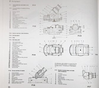
I do not have the book with me in moment to check all drawings, but I found the plan of the mortar
skecth F1/2 is showing under "4" the four Ring bolts for the tackles installed at the mortar bed. "12" are only for lifting so usually not belayed
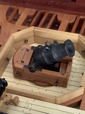
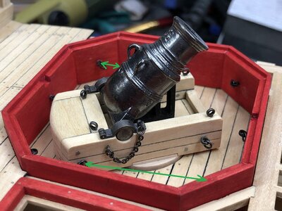
Here you see my Granado mortar of my section model - I made in each center of the walls a ringbolt - so all together 8 ringbolts in the walls
with these locations and tackles with hooks you are able to turn the mortar with two tackles
as an example I made two green arrows, which would be the positions of the tackles to turn the mortar to the left
During shooting the two tackles would be left and right to fix the bed, so that it is not able to turn.
Thanks, Uwe!
Kurt Konrath
Kurt Konrath
Dave the scratch made blocks are a step above on your model. Looking forward to seeing them in the rigging of the gun pit.
Great work Doc all around. You're another guy with the uber clean work ! not easy !
- Joined
- Sep 14, 2020
- Messages
- 152
- Points
- 88

Doc, Great pictures thru the entire build! I know accuracy is important, but we know that every Captain had his preferences on how a ship was rigged, decorated, and armored. So how do we build a historically accurate model unless we know the last ship captains preferences?


