Bonhomme Richard - Pear Cross section kit (with scratch duplicate using alder) Unicorn Model

DHL delivery from China Today!!! I'll post a few pictures from the unboxing below. Next post, I'll discuss my thoughts on making a duplicate with a bunch of Alder I have from a recent project.

First impressions:
1. Kit arrived via DHL in Eight days! It was well packed and looked pristine when I removed the exterior wrapping (photo 1).
2. There is a very large plan sheet (photo 2) is just 1/4 of the sheet. Printing is clear and precise. Translations from Chinese to English look adequate.
3. There is also a set of smaller drawings on a dozen or so sheets that show specific instructions and details (photo 3). Again, clear images and translations look adequate.
4. The wood (pictures 4 &5) looks like quality fine grain wood. It seems a slightly shade of pink than other pear wood I've worked with. We'll see how it sands and accepts stains/oils/etc. The laser etching is extremely fine and accurate and it doesn't look like the char extends too deep...more to follow as I begin detaching pieces.
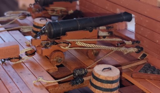
5. The accessories look fine. Cannons, deadeyes and blocks look excellent (photo 6). Much of this may be substituted or swapped out (line, wire, etc) as I customize and fine tune things.

The construction cradle sheets look very accurate and substantial enough to keep things aligned.

View attachment 424218

View attachment 424219

View attachment 424220

View attachment 424221

View attachment 424222

View attachment 424223
Hallo @BradNSW
we wish you all the BEST and a HAPPY BIRTHDAY
Birthday-Cake
Enjoy your special day
 
Thanks for all the well-wishes on my birthday!

Some small progress during the Truck Rally and Birthday!

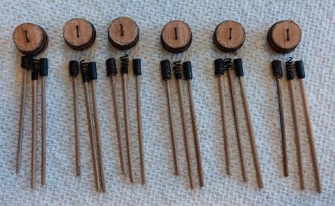
First, some close-up photos of the three tools and water barrels for each cannon position:
20241009_143614.jpg20241009_143730.jpg
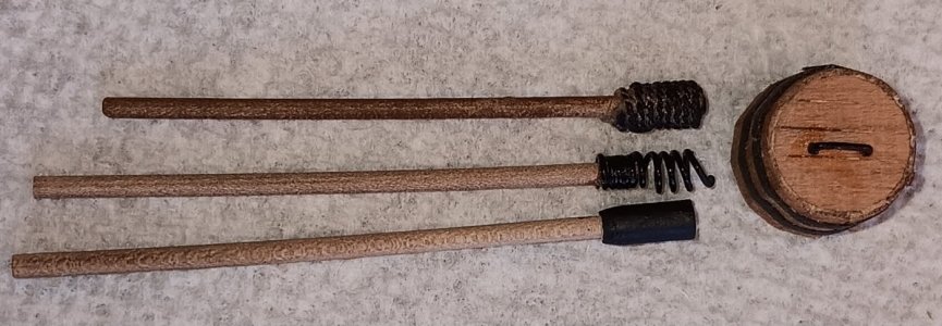
1. The Sponge (top tool) has two layers of (.025"/.63mm) rigging thread wrapped around a dowel. All dowels were run through a draw plate to a thickness of two scale inches for the handles. Two wraps of the .63mm thread equaled the diameter of the cannon barrel. This tool was soaked in water, then run through the barrel to extinguish any leftover powder embers.
2. The Wormer (middle tool) was made by glueing 4 tight wraps of 24-gauge jewelry wire around the handle. Then looser wraps around a slightly thicker toothpick, so the diameter was the same as the cannon barrel. This tool caught and removed any leftover wadding/powder/soot/etc.
3. The Rammer (bottom tool) was made from a dowel that was the diameter of the barrel. One end was drilled (and slightly tapered), then attached to the handle. This tool pushed the cannonball and "wadding" tightly into the powder charge. The wadding had to be tight, to ensure the cannonball did not roll out of the barrel, as the ship rolled!!
4. The water barrel was always wider at the bottom to keep it from tipping over (stability) and narrower/covered at the top (which kept water from sloshing out).

The Wormer and Rammer were painted black. A black "sharpie" was used to color the sponge, so it appears to be more of a sponge material.

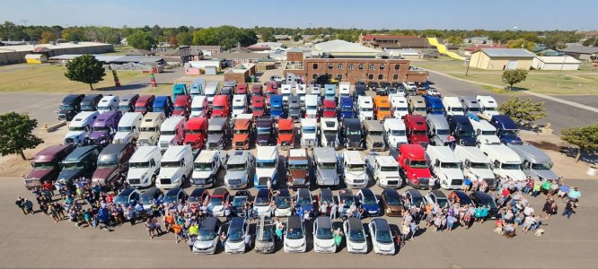
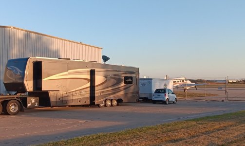
All of the trucks (and small "Smart" cars some carry on the back of their trucks) lined up for a photo at the fairgrounds. We had a wonderful BBQ dinner afterwards...good times for all involved!!
462704226_10222822268299917_1094395478434257857_n.jpg
Our truck is the white one and our Smart car is the white one, with the black roof...:)!
 
Thanks for all the well-wishes on my birthday!

Some small progress during the Truck Rally and Birthday!

First, some close-up photos of the three tools and water barrels for each cannon position:
View attachment 476498View attachment 476497
1. The Sponge (top tool) has two layers of (.025"/.63mm) rigging thread wrapped around a dowel. All dowels were run through a draw plate to a thickness of two scale inches for the handles. Two wraps of the .63mm thread equaled the diameter of the cannon barrel. This tool was soaked in water, then run through the barrel to extinguish any leftover powder embers.
2. The Wormer (middle tool) was made by glueing 4 tight wraps of 24-gauge jewelry wire around the handle. Then looser wraps around a slightly thicker toothpick, so the diameter was the same as the cannon barrel. This tool caught and removed any leftover wadding/powder/soot/etc.
3. The Rammer (bottom tool) was made from a dowel that was the diameter of the barrel. One end was drilled (and slightly tapered), then attached to the handle. This tool pushed the cannonball and "wadding" tightly into the powder charge. The wadding had to be tight, to ensure the cannonball did not roll out of the barrel, as the ship rolled!!
4. The water barrel was always wider at the bottom to keep it from tipping over (stability) and narrower/covered at the top (which kept water from sloshing out).

The Wormer and Rammer were painted black. A black "sharpie" was used to color the sponge, so it appears to be more of a sponge material.

All of the trucks (and small "Smart" cars some carry on the back of their trucks) lined up for a photo at the fairgrounds. We had a wonderful BBQ dinner afterwards...good times for all involved!!
View attachment 476499
Our truck is the white one and our Smart car is the white one, with the black roof...:)!
Good morning Brad. Sure looks like you had a wonderful birthday yesterday. As always your modelling is brilliant, I love the details you include. Ahh I see your truck and smart car clearly..... ROTF . Cheers grant
 
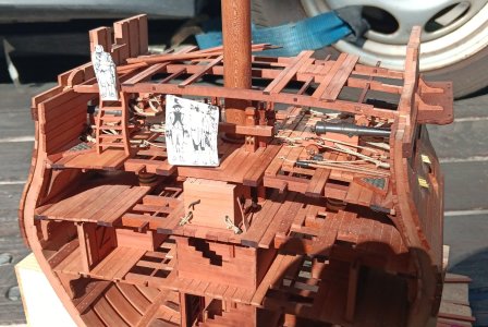
Shipyard is sailing over the rolling waves of wheat, sorghum, and corn, that is Kansas! Some progress on the top deck (quarterdeck) of the BHR cross-section.

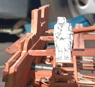
Below picture show the same issue Signet had on his kit. The cross beams were significantly short (4mm). At the direction of Midshipman Newbee, PO Brutis added scarf joints to lengthen them. The Shipyard Admiral came by and gave Midshipman Newbee a spot promotion to ENSIGN, for his initiative.
First picture shows PO Brutis by the beam extensions and Second picture shows the ADM minting the new ENSIGN!
20241016_111848.jpg20241016_111838.jpg

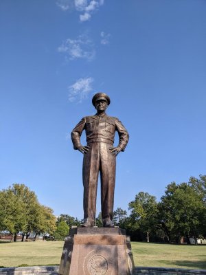
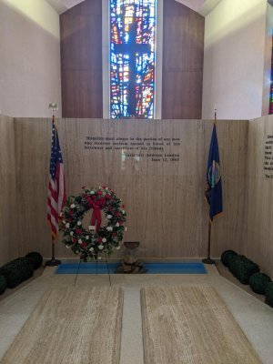
Finally, some pictures from the Eisenhower Presidential Library, in Abeline, KS. The iconic statue, as a 5 Star General and the final resting place for the president and his wife, Mamie.
eisenhauer.jpgeisenhauer grave.jpg

Today we tour my childhood home of Fort Leavenworth, KS.
 
Ensign Newbee rigged up an overhead rack for "stowing the cannon tools" (Sponge, Wormer and Rammer). When stowed for sea, they will be secured in the overhead rack (see 3 photos below).
20241017_165601.jpg20241017_165717.jpg20241017_165820.jpg

During Training or Combat, the tools would be taken down and staged, on the deck, ready for immediate use. In this case, the rammer is seating a cannonball during a training drill.
20241007_123132.jpg

We toured the Iowa Aviation Heritage Museum, and they let us park the mobile shipyard at the airfield for the night!! Lots and lots of superb plane models. From Company sponsored presentation models to a huge 15ft wingspan, RC controlled, B-17! Only three ship models. Two of the Yorktown and one of a Kidd class destroyer.
20241017_175731.jpg
 
Major modification to the kit.

Adding bracing around the main mast. The kit provides no additional bracing like the decks below.

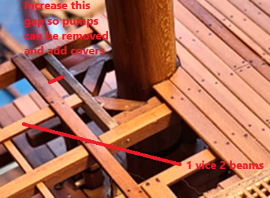
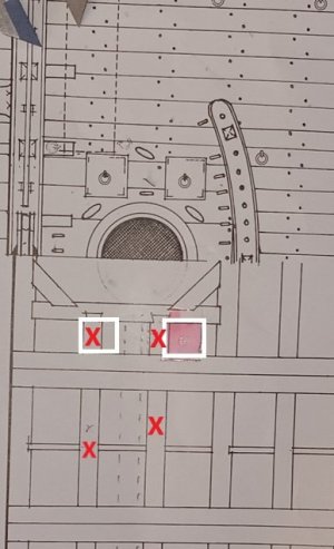
Boudroit's plans (see below) show bracing around the mast. Unfortunately, there is a large error in this drawing:
1. One side shows hatch covers to pull out the long pumps.
2. The other side shows two beams (with red X's) that would interfere with these openings.
3. ENS Newbee and PO Brutis proposed using ONE BEAM (the dotted grey line) between the hatches. This mirrors the bracing on the decks below AND has been approved by the shipyard superintendent!
4. This solution is similar to what Signet did (photo 2) with the mast bracing he designed, except the gap needs to be slightly wider to allow the pumps to be removed.

20241019_112435.jpgsignets mast bracking.png

Pictures will follow, as the shipyard mills some custom beams and manufactures some small covers for the pump removal holes.
 
Last edited:
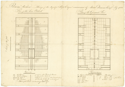
I am not sure if this would be of any use but I thought you and others doing cross sections might find it to be interesting. The below is a drawing from 1783 showing the stowage of ballast with a verbal description of the various surrounding items on the left and butts and barrels with description below on the right. It is for the HMS Edgar (74) 1779 but possibly useful for other rates and eras
Allan
1729766465627.png
 
I am not sure if this would be of any use but I thought you and others doing cross sections might find it to be interesting. The below is a drawing from 1783 showing the stowage of ballast with a verbal description of the various surrounding items on the left and butts and barrels with description below on the right. It is for the HMS Edgar (74) 1779 but possibly useful for other rates and eras
Allan
View attachment 479789
Allan,
This is extremely helpful in visualizing how the different size barrels were arranged! Thanks for sharing and I hope I can incorporate it when I get to loading the lower deck!!
 
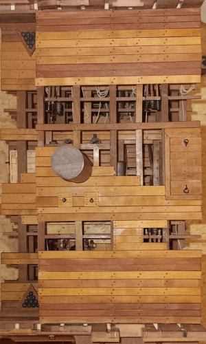
Significant milestone...all the decking is complete!

To refresh:
1. The kit had no planking around the mast.
2. Boudroit's drawings had an error (the beams marked by a red X, interfered with the small hatches to remove the dewatering pump, see below photo):
20241019_112435.jpg

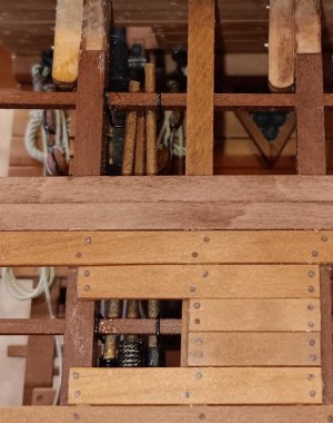
Below photos show the solution PO Brutis came up with.
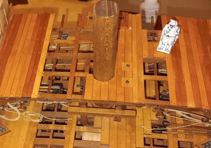
1. One beam BETWEEN the small pump hatches.
2. In the 1st photo, you can see the space created to pull the pumps for maintenance.
3. 2nd photo shows the small rings for removing these hatches.
4. All photos show the hold cover which was made using solid planking, just like the lower covers. Brutis did not use grating for this hatch cover because the quarterdeck is open, so ventilation was not an issue.
20241029_202355.jpg20241029_202206.jpg20241029_202253.jpg

Now the shipyard has to figure out how to deal with mast skirting that only goes around 3/4 of the mast???
 
Very nice solution and beautifully accomplished, Brad. Are you "on the road again"?
Paul,
Thanks for your interest. If the BHR did have a hatch to pull the pumps, this is the only solution I could envision.

Our Mobile Shipyard (RVing) season is coming to an end tomorrow, when we return to Loveland, CO for the winter. Our last month in the plains states was wonderful (extended family/friends and a nephew's wedding in Des Moines, IA). Tonight, we're in Kansas 200 miles East of Denver and winter is coming....temps in the 20's tonight.
 
Last small job before the mobile shipyard parks for the winter.

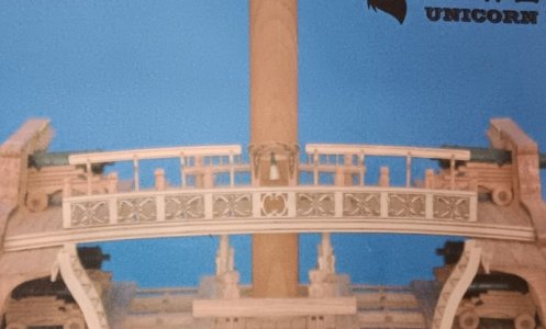
In the kit, they just glued the laser "char decorated" facade onto the quarterdeck beam. See photo below. Ens Newbee felt the "char decoration" looked tacky.
20241030_202836.jpg

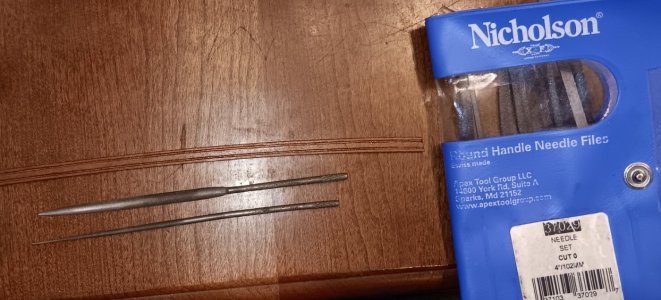
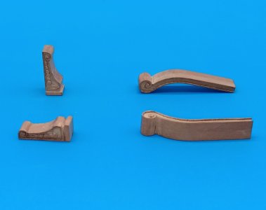
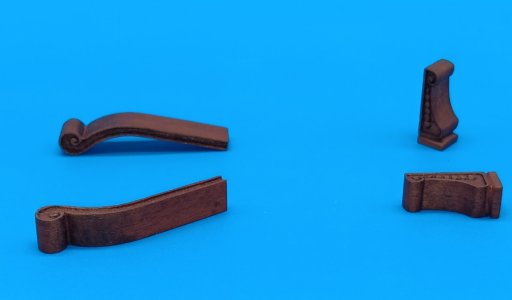
So Ens Newbee used Nicholson high quality micro jeweler's files to carve out along the char lines to create a 3-D facade. He then applied a coat of WATCO Dark Walnut Danish Wood Oil. These files are expensive, but they make "carving" micro details very easy. I used them almost exclusively to "carve" the figurehead on my scratch build of the HMS Serapis. The finish is comparable to 240-300 grit sandpaper.20241030_203601.jpg

Looking forward to the Mobile shipyard moving to the "Mile-High" basement workshop in Loveland. We won't have to box tools and parts up everyday, which slows progress considerably!!
 
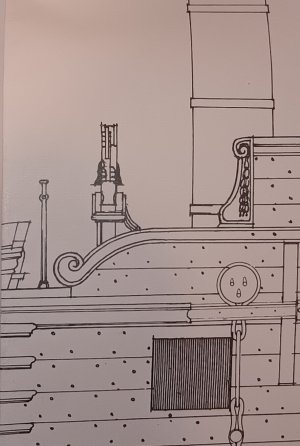
Here is a photo of the decorative rail and stanchion on the quarterdeck, from Boudroit's plans.

20241105_183101.jpg

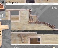
Ens Newbee didn't like the way the instruction photos just mounted the charred rail and stanchion.
instructions.jpg20241105_160812.jpg

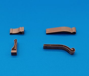
He and Petty Officer Brutis removed the offending char with some micro-files and then stained the pieces with WATCO Dark Walnut wood oil.
20241106_161225.jpg20241106_200924.jpg

These pieces look 100% better and after the top of the frames are leveled, they will be mounted and presented to the shipyard supervisor for approval.
 
Back
Top