Bonhomme Richard - Pear Cross section kit (with scratch duplicate using alder) Unicorn Model

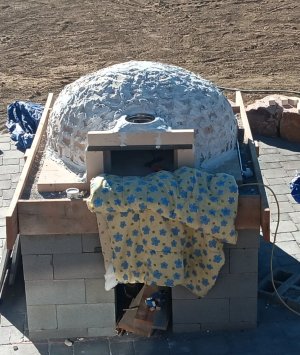
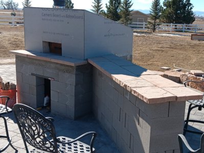
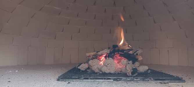
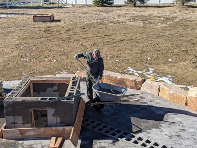
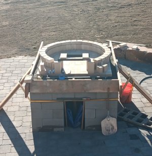
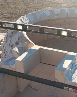
Two months since my last work (on the BHR). The ADM and I decided we needed a Pizza Oven to ring in the new year. I finished and we rang in the new year cooking woodfired pizza (see photos below). The BHR shipyard is once again operating, and I will post updates as progress is made. Sorry for the off-topic post but figured some could imagine similar ovens built on 17/18th century ships.

rebar and concrete.jpg20241112_144433.jpg20241115_150131.jpg20241120_134530.jpg20241130_111044.jpgpizza oven done.jpgcuring fire.jpg
 
Two months since my last work (on the BHR). The ADM and I decided we needed a Pizza Oven to ring in the new year. I finished and we rang in the new year cooking woodfired pizza (see photos below). The BHR shipyard is once again operating, and I will post updates as progress is made. Sorry for the off-topic post but figured some could imagine similar ovens built on 17/18th century ships.

View attachment 493041View attachment 493040View attachment 493042View attachment 493043View attachment 493044View attachment 493045View attachment 493046
Good morning Brad- now that is a proper Pizza oven! Beautiful view too. Cheers Grant
 
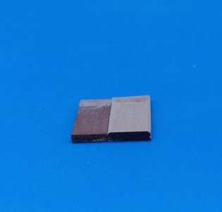
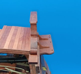
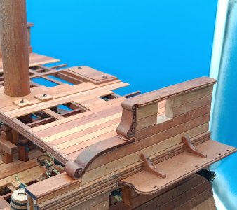
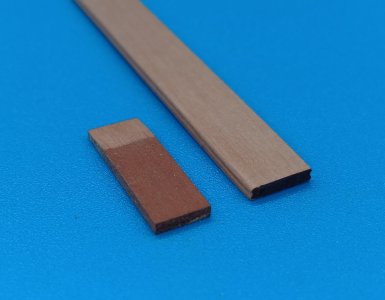
The taffrails proved to be more difficult than expected and I'm still not entirely satisfied. My issue with the kit:

I believe the pieces provided were: 1) Not thick enough or 2) Wide enough

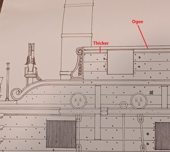
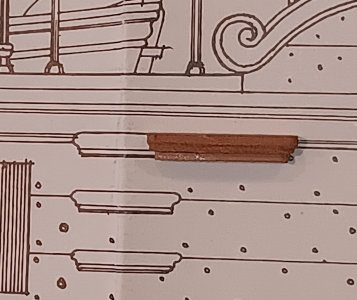
In Boudroit's plans the taffrails appear thicker than those provided and depict a decorative ogee.
20250104_134324.jpg

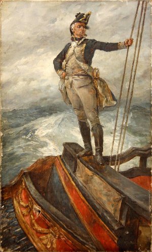
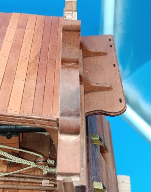
In most photos or paintings, the taffrails are slightly wider than the frames they sit atop (see dashing CAPT standing atop the taffrail)
William_Heysmann_Overend_Naval_Captain_on_the_Poop_deck_taffrail.jpg

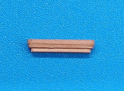
SO, I made mine thicker and slightly wider than those provided in the kit and added the decorative ogee detail.
20250104_134559.jpg

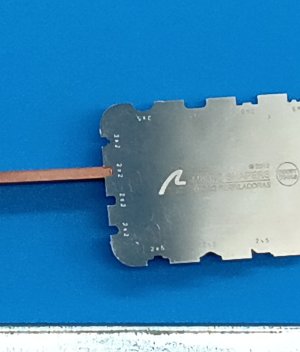
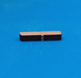
I find the profile tools that can be purchased very difficult to work with. In this case the smallest I had was too narrow and the next size was too large. See photo:
20250104_135102.jpg

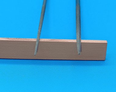
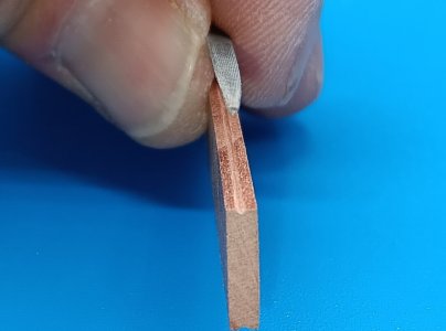
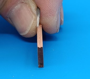
My solution has been to use jeweler's files. Photo 1 shows a triangle and circle file. Photo 2 shows how a couple of quick passes with the triangle file creates a reference groove in the middle. Photo 3 shows how this triangle groove is made circular to produce the rounded decorative ogee. Hopefully this technique is useful to someone on the forum.

20250104_135231.jpg20250104_140053.jpg20250104_140536.jpg

The final difficulty was the curvature of the frame and the deviation from perpendicular. This decorative piece had to be beveled at the base to follow the contour of the frame and I'm not completely happy with the gap. I will see what some sawdust and stain can do to hide the small defect.
20250105_114918.jpg20250105_115253.jpg


It's good to be working on the BHR again!

20250104_140749.jpg

20250104_133926.jpg
 
Last edited:
Spent some time modifying the accommodation ladder to the quarterdeck. The kit provided a very basic outline/shape (see below).
20250110_103044.jpg

Comparing it to the Boudroit drawing, it was clear that piece was too thin and needed an ogee profile.
20250110_103219.jpg

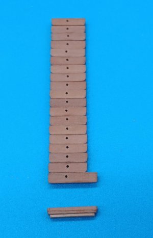
After a morning setting up a mass production line, this is what is rolling off.
20250110_120152.jpg20250110_120439.jpg

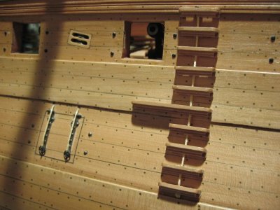
I'm always concerned about use in "real life", with pitching seas and salt spray. Climbing this, with no place for the fingers to grip, except a flat top would be near impossible. My solution will be to incorporate a rope, through the steps, similar to the photo below from a build log by Karl (aka Jeronimo) from (Nastätten - Rhein-Land-Pfalz - Germany) on the Nautical Research Guild:
karl rope on accomdaton ladder.jpg
 
Spent some time modifying the accommodation ladder to the quarterdeck. The kit provided a very basic outline/shape (see below).
View attachment 494407

Comparing it to the Boudroit drawing, it was clear that piece was too thin and needed an ogee profile.
View attachment 494404

After a morning setting up a mass production line, this is what is rolling off.
View attachment 494408View attachment 494409

I'm always concerned about use in "real life", with pitching seas and salt spray. Climbing this, with no place for the fingers to grip, except a flat top would be near impossible. My solution will be to incorporate a rope, through the steps, similar to the photo below from a build log by Karl (aka Jeronimo) from (Nastätten - Rhein-Land-Pfalz - Germany) on the Nautical Research Guild:
View attachment 494421
Nice steps, Brad. And that ‘inside rope’ is a better option then one hanging besides.
Regards, Peter
 
Paul, Peter and Tobias, I Thank You for the encouraging words as I work on small modifications to the kit. Very motivating.

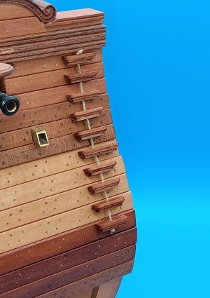
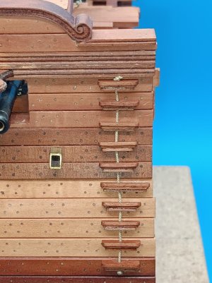
Below are the pictures documenting the final steps in making the quarterdeck access ladder. I'm happy with the result but, as you see in the last, head-on picture, the rope zig-zags ever so slightly, in spite of all the efforts I made to line things up perfectly. Hardly noticeable with the naked eye but apparent in the pictures.

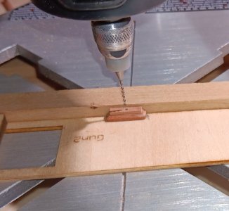
1. A jig on the Dremel drill press to center the rope hole in each step.
20250111_120817.jpg

22. The steps with holes drilled in the center.
20250111_122511.jpg

3. The finished result. I'd be confident climbing this in heavy seas, with the rope for hand holds.
20250111_150705.jpg20250111_150816.jpg
 
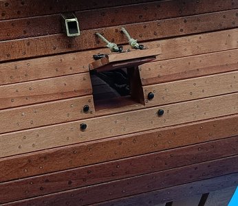
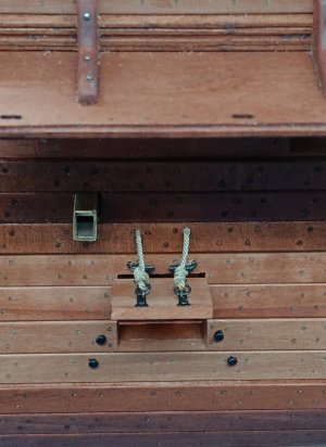
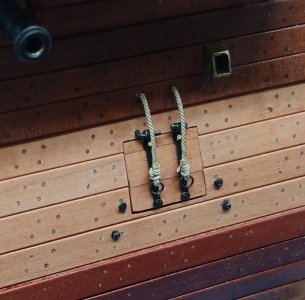
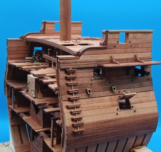
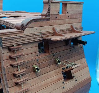
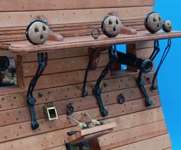
Main deck gun covers are installed. The main cannons on this deck, are stowed for sea, SO I opted to have one cover (downwind) stowed, as the freeboard would be too small and waves would enter. The upwind gun cover is open to allow a little more ventilation, while cruising on this tact.

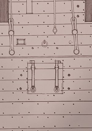
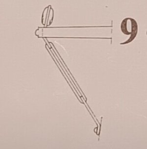
1. Here is the picture from Boudroit (a). Note the two external bolts are in line on either side of the hatch. You will see in the final photos, mine are staggered, as my interior belaying bolts are also staggered (b).

a. b.
20250113_105309.jpg20240825_143429.jpg

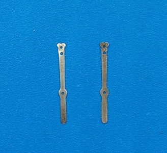
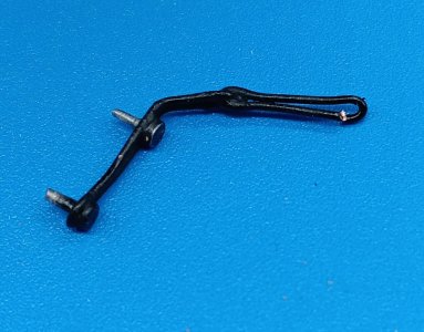
2. I filed the tabs off the metal gun cover straps. (These are included in the kit.
20250113_105407.jpg20250113_115535.jpg

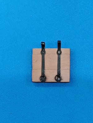
3. Next, I blackened the metal fittings and attached them to the ports.
20250113_161437.jpg

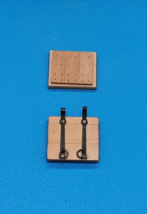
4. I also added reinforcement to the covers, using strips perpendicular to the hull framing. Nails were simulated using pin-holes. This detail is not included in the kit, as the covers are to be built in the closed position.
20250113_155517.jpg

5. The final results on both sides (open and shut). (The ropes are .035" and .012") and not included in the kit. The external bolt are not included in the kit either.
20250115_124000.jpg20250115_124052.jpg20250115_124150.jpg

I hope some folks find the step-by-step pictures and addition of the ropes, rings and bolts helpful.

20250113_114742.jpg
 
Last edited:
Paul,

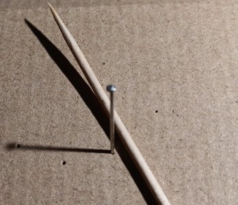
The bolt heads were made from small pins (see photo) with toothpick for reference.

The "head" is .073inches = 3.5" for the bolt heads at 1/4".

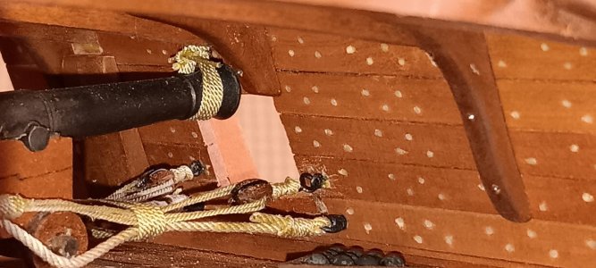
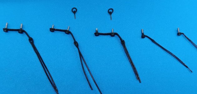
I think that is a pretty good scale representation and matches the interior recoil bolts (at the end of the recoil ropes in the picture w/blue background).

20250115_151752.jpg20240925_140513.jpg
 
Main deck gun covers are installed. The main cannons on this deck, are stowed for sea, SO I opted to have one cover (downwind) stowed, as the freeboard would be too small and waves would enter. The upwind gun cover is open to allow a little more ventilation, while cruising on this tact.

1. Here is the picture from Boudroit (a). Note the two external bolts are in line on either side of the hatch. You will see in the final photos, mine are staggered, as my interior belaying bolts are also staggered (b).

a. b.
View attachment 495320View attachment 495329

2. I filed the tabs off the metal gun cover straps. (These are included in the kit.
View attachment 495321View attachment 495323

3. Next, I blackened the metal fittings and attached them to the ports.
View attachment 495325

4. I also added reinforcement to the covers, using strips perpendicular to the hull framing. Nails were simulated using pin-holes. This detail is not included in the kit, as the covers are to be built in the closed position.
View attachment 495324

5. The final results on both sides (open and shut). (The ropes are .035" and .012") and not included in the kit. The external bolt are not included in the kit either.
View attachment 495317View attachment 495318View attachment 495319

I hope some folks find the step-by-step pictures and addition of the ropes, rings and bolts helpful.

View attachment 495322
That are very nice and detailed covers, Brad. And to see all the steps.
Regards, Peter
 
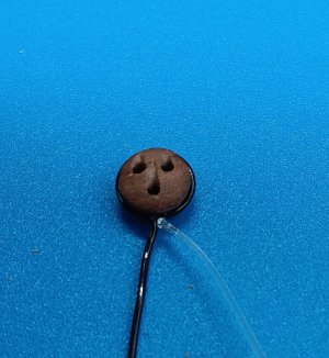
Expecting below zero temperature and lots of snow, so I did some experimenting with the deadeyes and chainplates.

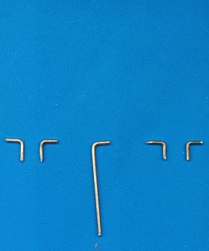
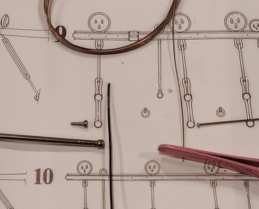
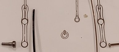
1. A photo of the chainplate diagram by Boudroit. On the right, you can see the pins and wire provided with kit. The wire is half the proper diameter, and the pins are about 60% of the diameter needed. So off to Home Depot, where I bought some finishing nails. The left shows a finishing nail, that I put in the mini-lathe and turned to get the proper diameter head and then necked the shaft down to fit the holes I will drill. The left also shows the 20GA bead wire I will use to rig the deadeyes and chainplate fasteners.
20250117_145750.jpg

2. Photos of the prototype deadeye. Mass production will begin tomorrow.

20250117_150004 (1).jpg20250117_152550.jpg
 
Expecting below zero temperature and lots of snow, so I did some experimenting with the deadeyes and chainplates.

1. A photo of the chainplate diagram by Boudroit. On the right, you can see the pins and wire provided with kit. The wire is half the proper diameter, and the pins are about 60% of the diameter needed. So off to Home Depot, where I bought some finishing nails. The left shows a finishing nail, that I put in the mini-lathe and turned to get the proper diameter head and then necked the shaft down to fit the holes I will drill. The left also shows the 20GA bead wire I will use to rig the deadeyes and chainplate fasteners.
View attachment 495784

2. Photos of the prototype deadeye. Mass production will begin tomorrow.

View attachment 495785View attachment 495787
Ha! I'm doing the same thing right now!
 
Shoveled lots of snow off our 80ft driveway, so only managed to place all the external cannon bolts.

The main gundeck bolts, as previously discussed were .073" pin heads (3.5" scale bolts). On the upper two decks I used smaller tacking pin heads (.05" pin heads = 2.4" scale bolts), as the guns were significantly smaller/lighter.

Barring more snow, I should be able to tackle the chainplates and deadeyes tomorrow.

20250118_161709.jpg20250118_161859 (1).jpg
 
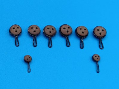
Shipyard focused on rigging the deadeyes as temps outside for the last two days were zero to -20 degrees!

Lots of pictures below explaining how I deviated from the kit. Hopefully they are helpful to someone on this forum!

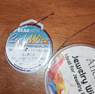
As mentioned previously, the wire diameter was too small by 50%, and they only provided one size wire. I ended up using two different jewelry wire sizes (20 gauge and the other is slightly less than half that size.

20250121_110412.jpg

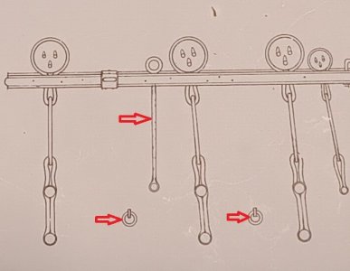
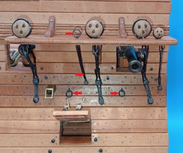
The Boudroit diagram below shows the area of the cross section. The red arrows indicate items that were not included in the kit.
20250121_105405.jpg

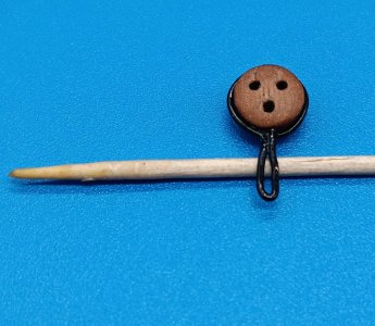
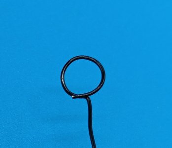
To make the deadeye's, I wrapped a deadeye tightly, created a 90-degree bend, and then popped out the deadeye. With the deadeye out, I trimmed the wire to be flush, then reinserted the deadeye and put a small drop of instant glue.
20250119_093017.jpg20250119_093223.jpg20250119_102244.jpg

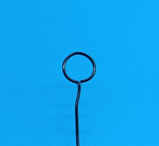
The tag end was then bent 180 degrees around tweezers, then trimmed to the correct length and a drop of instant glue was applied. For the smaller deadeyes, I used the small diameter jewelry wire.
20250119_111750.jpg

For the chainplates, I turned bolts on the lathe to be the proper diameter. The pins on the right, provided in the kit, were only 40% too small.
20250117_145750.jpg

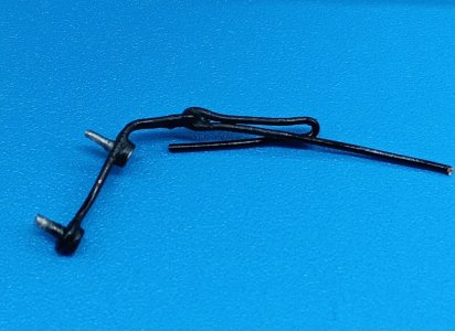
The bolts were then crimped on bends in the wire and a drop of instant glue was applied. These were left overnight. Then the ends were bent up at the angle from Boudroit's drawing (second photo). A second chain link was inserted and bent to the correct length. The ends were trimmed flush and a drop of instant glue applied.

20250121_085707.jpg20250121_105514.jpg20250121_085904.jpg

After many tiny adjustments, with tweezers and small pliers, all the pieces for the port side were ready for installation.

20250121_081114.jpg

Below is the final result. Items with the red arrows were not included in the kit but are on the Boudroit plans. In addition, all the wire and bolt heads were substitutions, as those in the kit were much too small.

20250121_103326.jpg20250121_103436.jpg20250121_105405.jpg

I am debating whether I should paint the bolts on the knees black. They were installed months ago.

My hesitation...I'm worried about paint bleeding into the wood around the bolts!!!

All the bolts on interior knees are NOT painted and in places where I couldn't paint them if I wanted....we will see what the shipyard superintendent decides!
 
Shipyard focused on rigging the deadeyes as temps outside for the last two days were zero to -20 degrees!

Lots of pictures below explaining how I deviated from the kit. Hopefully they are helpful to someone on this forum!

As mentioned previously, the wire diameter was too small by 50%, and they only provided one size wire. I ended up using two different jewelry wire sizes (20 gauge and the other is slightly less than half that size.

View attachment 496536

The Boudroit diagram below shows the area of the cross section. The red arrows indicate items that were not included in the kit.
View attachment 496537

To make the deadeye's, I wrapped a deadeye tightly, created a 90-degree bend, and then popped out the deadeye. With the deadeye out, I trimmed the wire to be flush, then reinserted the deadeye and put a small drop of instant glue.
View attachment 496521View attachment 496522View attachment 496523

The tag end was then bent 180 degrees around tweezers, then trimmed to the correct length and a drop of instant glue was applied. For the smaller deadeyes, I used the small diameter jewelry wire.
View attachment 496525

For the chainplates, I turned bolts on the lathe to be the proper diameter. The pins on the right, provided in the kit, were only 40% too small.
View attachment 496538

The bolts were then crimped on bends in the wire and a drop of instant glue was applied. These were left overnight. Then the ends were bent up at the angle from Boudroit's drawing (second photo). A second chain link was inserted and bent to the correct length. The ends were trimmed flush and a drop of instant glue applied.

View attachment 496527View attachment 496540View attachment 496528

After many tiny adjustments, with tweezers and small pliers, all the pieces for the port side were ready for installation.

View attachment 496526

Below is the final result. Items with the red arrows were not included in the kit but are on the Boudroit plans. In addition, all the wire and bolt heads were substitutions, as those in the kit were much too small.

View attachment 496529View attachment 496541View attachment 496537

I am debating whether I should paint the bolts on the knees black. They were installed months ago.

My hesitation...I'm worried about paint bleeding into the wood around the bolts!!!

All the bolts on interior knees are NOT painted and in places where I couldn't paint them if I wanted....we will see what the shipyard superintendent decides!
Very nice work, my friend! This looks wonderful!
 
Paul, Peter and Tobias, I Thank You for the encouraging words as I work on small modifications to the kit. Very motivating.

Below are the pictures documenting the final steps in making the quarterdeck access ladder. I'm happy with the result but, as you see in the last, head-on picture, the rope zig-zags ever so slightly, in spite of all the efforts I made to line things up perfectly. Hardly noticeable with the naked eye but apparent in the pictures.

1. A jig on the Dremel drill press to center the rope hole in each step.
View attachment 494531

22. The steps with holes drilled in the center.
View attachment 494532

3. The finished result. I'd be confident climbing this in heavy seas, with the rope for hand holds.
View attachment 494533View attachment 494534
Another one of those fine pesky details you notice, but most of use probably would not have noticed until you call it out. :p
 
Shipyard focused on rigging the deadeyes as temps outside for the last two days were zero to -20 degrees!

Lots of pictures below explaining how I deviated from the kit. Hopefully they are helpful to someone on this forum!

As mentioned previously, the wire diameter was too small by 50%, and they only provided one size wire. I ended up using two different jewelry wire sizes (20 gauge and the other is slightly less than half that size.

View attachment 496536

The Boudroit diagram below shows the area of the cross section. The red arrows indicate items that were not included in the kit.
View attachment 496537

To make the deadeye's, I wrapped a deadeye tightly, created a 90-degree bend, and then popped out the deadeye. With the deadeye out, I trimmed the wire to be flush, then reinserted the deadeye and put a small drop of instant glue.
View attachment 496521View attachment 496522View attachment 496523

The tag end was then bent 180 degrees around tweezers, then trimmed to the correct length and a drop of instant glue was applied. For the smaller deadeyes, I used the small diameter jewelry wire.
View attachment 496525

For the chainplates, I turned bolts on the lathe to be the proper diameter. The pins on the right, provided in the kit, were only 40% too small.
View attachment 496538

The bolts were then crimped on bends in the wire and a drop of instant glue was applied. These were left overnight. Then the ends were bent up at the angle from Boudroit's drawing (second photo). A second chain link was inserted and bent to the correct length. The ends were trimmed flush and a drop of instant glue applied.

View attachment 496527View attachment 496540View attachment 496528

After many tiny adjustments, with tweezers and small pliers, all the pieces for the port side were ready for installation.

View attachment 496526

Below is the final result. Items with the red arrows were not included in the kit but are on the Boudroit plans. In addition, all the wire and bolt heads were substitutions, as those in the kit were much too small.

View attachment 496529View attachment 496541View attachment 496537

I am debating whether I should paint the bolts on the knees black. They were installed months ago.

My hesitation...I'm worried about paint bleeding into the wood around the bolts!!!

All the bolts on interior knees are NOT painted and in places where I couldn't paint them if I wanted....we will see what the shipyard superintendent decides!
Some very nice detailed and explained ironwork, Brad. :) They look great on the model.
Regards, Peter
 
Back
Top