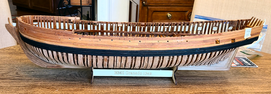
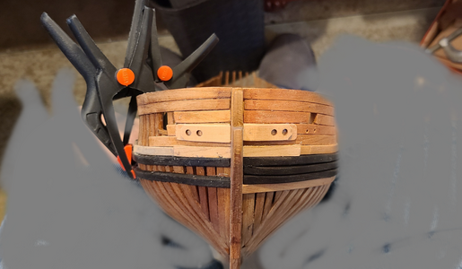
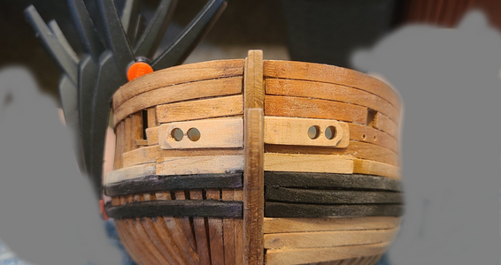
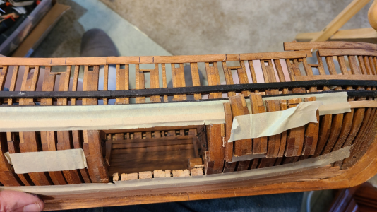
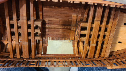
CAF Granado 1/48 PoF Bomb Vessel by Signet

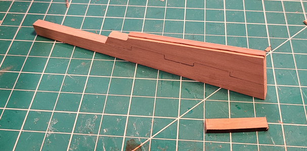
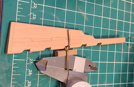
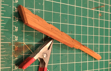
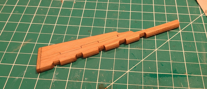
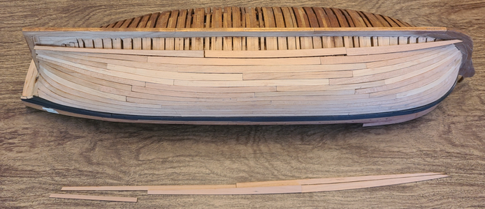
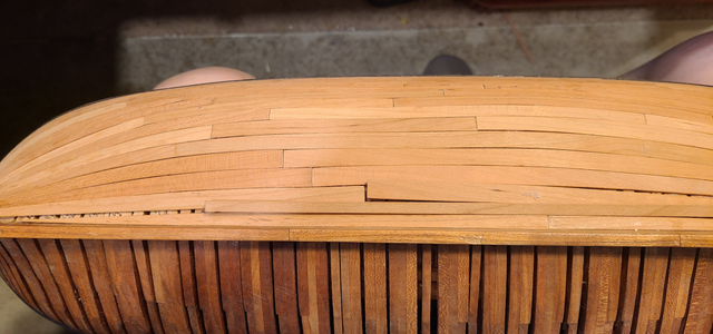
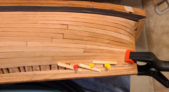
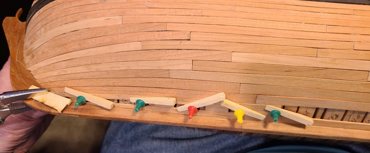
Since I didn't want to wait for the material to make the inserted planking, I decided to make do with extra planking I have from not intending to complete planking on the starboard side of the ship. If I'd known about this sooner, I'd have done it differently, but I had to make do. Basically, I had to insert another row of planking between existing planking row #4, and thicker row #5 yet to be added. The most accurate would be to duplicate row #4, as I had that from the other side. But that would put all of the planking joints right next to each other, which wouldn't do. So I compared row #3 with row #4, and found the pieces pretty close in shape, but with joints at different locations. Here's plank 4a, one that's on the model, with plank 3a:
1722998230531.png
It's pretty close, but longer. Not exact, but I hoped it would do. So I used this 3a plank along with unused 4b, 4c and 4d from the other side, to complete the extra row (call it 4+) of planking.

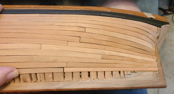
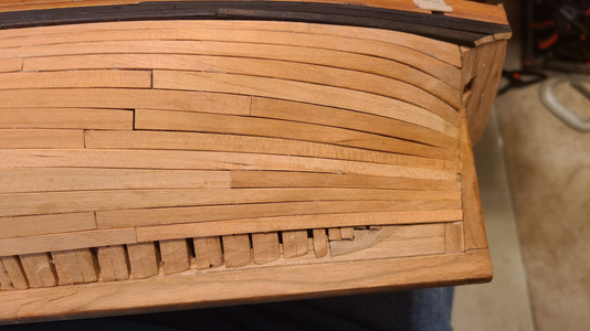
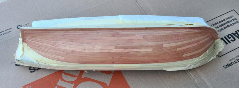
After inserting that planking row, I then added row 5, which is thicker. I wanted to color the wales black while off the model, so went ahead and gave the planking one coat of Watco Danish Oil to seal it:
1722998433209.png
It's unfortunate there is as much color variation in the planking as there is, but different sheets have slightly different colors. Sometime all planks in a row come from the same sheet (like row 5), but usually they do not, so they vary in color. I may try to blend this a bit later, if it's very noticeable at that time, but not now.

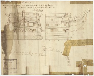
I now have the required 5 rows of planking plus row 1 at the forecastle. And I sanded very little off of the planks in width, and felt confident about the location of the top planking row, as its height and contour was dictated by the frame heights, which were trimmed to match the dock/jig top contour. So I'll compare where the wales will end up compared to the drawing:

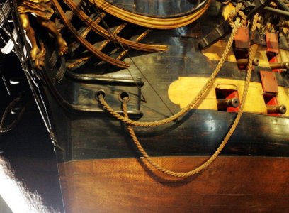
The lowest of the 3 wales should end up just below the split in the stem structure (flipped to match photo):
1722999230408.png
Holding the 6a through 8a wales pieces in place, it shows that it's at about the right height:
1722999400031.png

Now, checking the wales at the stern in the same way:
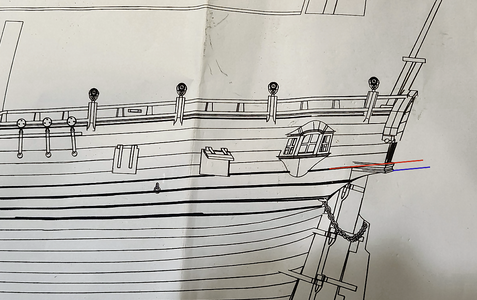
1722999454915.png
The top Wales should start ABOVE the curve beginning at the stern, about at the bottom of the windows. But in my case:
1722999518982.png
it looks like there is an entire planking missing. The installed planking is about 5mm higher than it should be for the row 5 2.1mm thick planking row to fit in the intended position. I thought maybe I sanded too much off the first four plank widths, but no - they measure 28mm overall, while the drawing shows them only 26mm. So if the bottom of the stern is right, then the top is too high by 5 + 28 - 26 = 7mm! That can't really be. Not if the dock/jig is correct, and I have to assume it was. CAF instructions tell you to install thicker planking rows 5-8 first, then up and down from there, but there is no way I could tell exactly where it should go, and it would substantially change the top profile, which /should/ be correct.

I'm very tempted at this point to add yet another planking row (in addition to the missing row I added) to make this height correct. But I'd have to remove the thick row first, and have used all the planking of that thickness. And, it would lower the wales at the front, I think, too much and cause problems there. All I can think to do, without ripping out a substantial amount of work and destroying pieces in the process, is to start the wales (planking row 6) as I expected to, below thicker planking row 5. I have to replace the piece 6d with something longer, but I think I can find some wales planking I'm not using for that. So I think that's the way I will go.

I will say that sometimes laser-cut pieces made to exact theoretical dimensions is nice. But so much of the time it means you can't use a part as intended. Like in this case, I can't use 6d because of the curved bottom. If it was just straight, I could have. And no matter where it ends up, I will have to trim and sand to get a good fit at the stern, so the curve isn't really much help even if everything is exact.

Anyhow, going as I've explained seems to be the only viable alternative, and I'm hoping it won't change the looks too much or cause other unanticipated problems. (Like stern planking not being high enough to fit when I get to the keel.) :rolleyes:
 
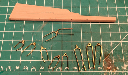
Since I've been confused lately about this planking problem described above, my attention wandered to the rudder. As Uwek had done, I wanted to make the rudder a bit closer to the original as shown in Goodwin's book. While the rudder should be constructed of 3 main pieces of wood, rather than the kit's 2 pieces, that would have required a completely new rudder. I considered adding a row of "joints" to simulate the 3rd piece, but as the kit parts are each roughly half the width of the rudder, the original was 3 pieces each a third of the width. So that wouldn't work. I did decide to add the sole (wear) piece at the bottom and the thin backpiece:
1723000637067.png
I used scrap cherry for the sole plate, because it should show up with its grain ad 90 degrees to the rudder material. For the backpiece I used a piece of pear, which I hoped would show up somewhat (but not too much) against the cherry. If it was cherry, it would blend right in and be unnoticeable.

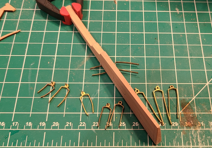
I tried to taper the rudder to better match the original, then took a look at the hinge pieces:
1723000760302.png
There was no way to taper the rudder completely accurately without also tapering the Inner Post it is attached to, and then also the keel width, etc. (Yikes!). So I did what I could to give the impression that the rudder and its attachment is tapered. Also rounded along the hinge end:
1723000886489.png

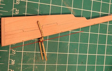
I then had to cut the notches for the hinges, so that the rudder would mount close to the Inner Post.
1723000964192.png
The red line shows the depth required to entirely bury the hinge into the rudder, allowing the rudder to touch the Inner Post. The drawing shows about a 2mm gap between rudder and post, but Goodwin indicates it almost touches, so I needed to make deeper notches than the drawing shows for the hinges:

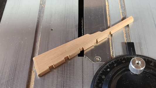
I cut the notches on my table saw to the required width, intending to round them at the bottom as shown on the drawings:
1723001133511.png
I made a little support at the correct angle (about 4 degrees) so that the notches would be perpendicular to the rudder center, not one side or the other, which is tapered.

Even with the notches being 1/8" deep, the space between rudder and post is more than I'd like:
1723001234287.png
I need to modify the post shape anyhow to accommodate the shape of the 'U' portion of the hinges, so I'll probably just cut them a bit deeper when mounted to fit them more closely.

I think the completed rudder looks okay, although the pear backpiece does not show up very much:
1723001343628.png
1723001355403.png

That's about it for today. I'm waiting for the Danish Oil and Wales blackening to dry well before adding them. Plus I want to sleep on the situation of the stern height being off and decide if my proposal is the best way to go.
 
I substituted a different 7-row piece for one of the 6-row to make it long enough, as mentioned previously. I forget which one, I think 7c or 7b. This has gotten very confusing, substituting a piece I don't think I'll use to replace one that is too short. It's all too easy to use a piece that I shouldn't. And there are extra pieces, too, like on sheet 3C there are four piece 7-d's, but 2 are printed backwards. I think I'll get through it though.

This is what she looks like with the first wales row installed and a few holes partially prepared:
1723066227137.png
I like the contrast of black with natural wood, and love using the Ecoline inks for staining wood. It's so much easier than paints, and I really like the finish. Thanks to Uwe for this idea (and many, many others).

Now to figure out how to lengthen the next wales row, which is also too short.
 
This hull is looking very good - good to hear that you are making also good experiences with the Ecoline-colours
 
2nd and 3rd row of of wales are now installed:
1723308283279.png
I decided that the port side of the hull is now plenty strong, so will not continue with thinner planking below the wales at this time.

Instead I measured from the top of the rail area to the first wales row, marked it with masking tape and added a continuous strip of masking tape to locate the row when applying to the starboard side, which will have a minimum of planking, to show the frames and structure within:
1723308434222.png
 
Both upper and lower wales are now on the starboard side:
1723492396667.png
I see the foremost lower wale has broken loose (again), after being glued and c-clamped overnight. Guess I need to do something better. I also added a bit of planking at the stem above the upper wales. This is to accommodate the reinforcements around the hawse holes, which will be added later. I'm tempted to add them now, but their height depends on the location of the upper and lower cheeks, which have to connect to the knee of the head, so I'll postpone that until later.

I want to add at least one, possibly more, strakes on this side to reinforce the openings I want to cut, but feel I need to finish the port side planking first, to see what plank(s) should be selected for this and where they will go. So that's what I'm doing now.
 
This hull is looking very good - good to hear that you are making also good experiences with the Ecoline-colours
An unexpected occurrence with the Ecoline colors is that when adding water to release a glue joint, they run onto other areas of wood, staining it somewhat. I thought these would be permanent (non-soluble) inks. In your experience, after painting with ink, do the surfaces need to be coated with clear varnish or something to seal them?
 
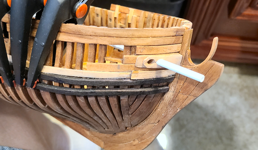
I went ahead and mounted the pieces around the hawse holes, because I didn't want to be drilling through all of that later:
1723661342243.png
After seeing the photo, I saw how far off the lower wale was in its location, so unglued and repositioned it better:
1723661388756.png
And drilled larger holes for the hawse holes as I'm making liners to go in there. Yeah, my poor workmanship really shows up at this scale, but it is what it is.

The drilled hawse holes chipped up the wood around a bit, but I hope to fill that after mounting the liners:
1723661483619.png
I'll be using plastic tubing with the proper ID for the hawse holes to create the liners:
1723661532771.png
The liners will be made and installed later.

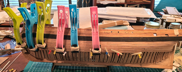
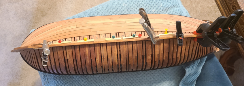
Larger clamps are necessary for me to add the planking below the wales:
1723661585905.png

Again, sorry about showing off my poor workmanship. It isn't as visible, to me, when working on the model, but really shows up in the photos. And yeah, I know I'll still be pleased with the result, and it's a great kit, but it is disappointing to see how my workmanship on this model compares to the builds of others. It kind of makes me want to not post photos about the build, but surely there's /someone/ out there who might be helped, or forewarned with my problems, or if nothing else, will realize there are models less well built than their own. :oops:
 
Continuing on with the port side planking:
1723945676322.png
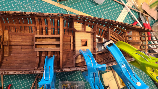
I've found that the chothesline clamps I've been using work pretty well, up to a point. I've recently had to add self-adhesive non-skid tape to the ends, which did not self-stick so are additionally held with rubber bands. They are about at their limit for lower planking, and tend to slip a bit. Thank goodness I'm doing things out of order (outer planking long before the instructions say to do it), as the clamps interfere with the fragile inner structures I've done so far:
1723945846750.png
At this point, I have a minimum of inner structure done, which gives good access to clamping surfaces. I've already inadvertently damaged the fragile room walls a bit (my apologies to the ship's Purser, whose cabin size was reduced with a deformed wall). I've therefore resorted to more and more tacks with tapered shims to keep the planks in position. But it's getting there. Lucky for me, planks require less bending and forcing into place as they near the keel. Fit of the planks has been fairly good in general, with most if not all gaps caused by me, rather than the kit, but will fill most of them prior to painting "white stuff" below the waterline.

I doubt the planking arrangement is very accurate, though, with no dropstakes or stealers as was the norm and is shown on Goodwin's drawings, plus the fact that a single plank can go from scale 18" wide to a scale 9" wide, which I think would not be done on the real ship. But again, most of that will be painted.

Again, I am entirely planking the port side hull of the model, with minimal planking in place and to be added to the starboard side, to allow internals to be better viewed. The hull structure is very strong, and will be more so once cross beams are added (after all planking), even after cutting away parts of some starboard frames, I think/hope.
 
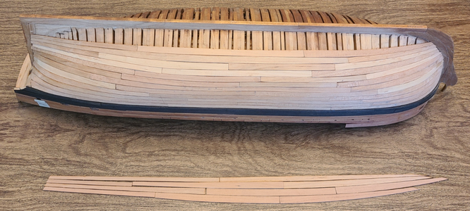
Hull planking worked reasonably well down to planking row 20. Row 21, however, was too short to span from stem to stern:
1724290746566.png
It's over an inch too short. So I examined the last four rows, 21 though 24:
1724290784513.png
Row 21 is at the bottom of the photo, arranged like it goes onto the hull. You can see it's far shorter than row 22 or even 23 and 24. So something's wrong there. I triple checked that I had the right pieces, and they are correct.

So I substituted plank 19b from the opposite side, assuming/hoping I wouldn't need or want that particular row on the open side:
1724290939611.png
The shape is quite similar, but longer, and can be made pretty much exactly to what I needed. It obviously fits better:
1724290986317.png
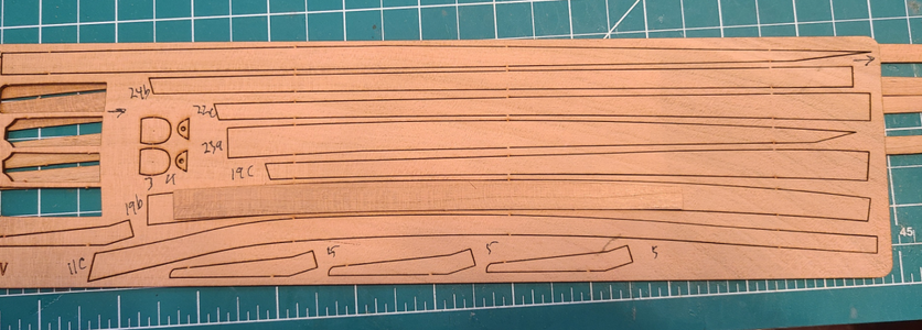
Part 21c when used to it's stated length also ended to close to the plank end above it:
1724291192524.png
Substituting the longer 19b plank for the 20b allowed me to move the joint back further:
1724291238048.png

Having now only 3 planking rows to go, I carefully measured the distance remaining along the hull, from lowest point of plank to the keel connection, and also measured row 24 widths to see how it would fit:
1724291311242.png
I modified the length of plank 24a to start further back from the stem, to allow room for 3 planks to go forward, and then mounted in it place:
1724291393134.png

Rather than use planking rows 22 and 23, I decided to put row 23 under 21, as it fit better, and decided rather than use row 22, to just use a couple of the many supplied 1.5x5mm strips to go between. Here I am planning the 1.5x5 strip, and determining how much of the row above to remove for it to fit:
1724291543590.png
Planking heights at the stem and center of the hull were such that I could have eliminated one entire row (for whatever reason), but as planking neared the stern at the sternpost, it required 3 planks, so inserting the 1.5x5 strip would work well:
1724291656683.png
I used small pieces of 1.5x5 strips to determine the required width of the plank above it, as well as to keep the spacing while gluing that row in place:
1724291718889.png
Here all planking rows are now in place except the 1.5x5 strip:
1724291759021.png
And when all is glued in place I had:
1724291788476.png
1724291807649.png
A lot of sanding and trimming is required on the planking, and there are gaps both longitudinally and at the ends, but most of this area will be painted "white stuff white", so I can use filler to improve it.

You will probably recall that I will not be splitting the hull horizontally, like most builders much better than I are doing, but I would like to give a better view to some internals.

So now I have to determine what added planking I want on the starboard side - a minimum, so as to provide some visibility of inner components and structure, but enough, hopefully, to strengthen the hull on that side and, hopefully, to allow some framing to be cut away to improve the view of the ship's innards. The fully planked side is amazingly strong, which is not surprising given all the frames and planking, and will be even stronger once cross beams are installed.
 
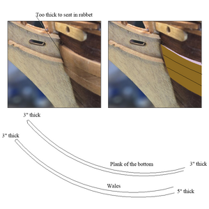
Sorry I am late to the party. I love that the kit provides spiled planking so all the strakes end at the rabbet. Maybe too late for this project, but thought you might be interested for the future. Regarding the wales, the thickness of these strakes has come up a few times on other logs. The wales, as well as the couple of thick strakes above and below the wales are tapered in thickness as they approach the bow so they can seat in the rabbet. The pic below is from another build but explains a bit better than words.
Allan
1724321254443.png
 
Hull planking worked reasonably well down to planking row 20. Row 21, however, was too short to span from stem to stern:
View attachment 466293
It's over an inch too short. So I examined the last four rows, 21 though 24:
View attachment 466294
Row 21 is at the bottom of the photo, arranged like it goes onto the hull. You can see it's far shorter than row 22 or even 23 and 24. So something's wrong there. I triple checked that I had the right pieces, and they are correct.

So I substituted plank 19b from the opposite side, assuming/hoping I wouldn't need or want that particular row on the open side:
View attachment 466296
The shape is quite similar, but longer, and can be made pretty much exactly to what I needed. It obviously fits better:
View attachment 466297
Part 21c when used to it's stated length also ended to close to the plank end above it:
View attachment 466300
Substituting the longer 19b plank for the 20b allowed me to move the joint back further:
View attachment 466301

Having now only 3 planking rows to go, I carefully measured the distance remaining along the hull, from lowest point of plank to the keel connection, and also measured row 24 widths to see how it would fit:
View attachment 466302
I modified the length of plank 24a to start further back from the stem, to allow room for 3 planks to go forward, and then mounted in it place:
View attachment 466303

Rather than use planking rows 22 and 23, I decided to put row 23 under 21, as it fit better, and decided rather than use row 22, to just use a couple of the many supplied 1.5x5mm strips to go between. Here I am planning the 1.5x5 strip, and determining how much of the row above to remove for it to fit:
View attachment 466319
Planking heights at the stem and center of the hull were such that I could have eliminated one entire row (for whatever reason), but as planking neared the stern at the sternpost, it required 3 planks, so inserting the 1.5x5 strip would work well:
View attachment 466320
I used small pieces of 1.5x5 strips to determine the required width of the plank above it, as well as to keep the spacing while gluing that row in place:
View attachment 466323
Here all planking rows are now in place except the 1.5x5 strip:
View attachment 466324
And when all is glued in place I had:
View attachment 466325
View attachment 466326
A lot of sanding and trimming is required on the planking, and there are gaps both longitudinally and at the ends, but most of this area will be painted "white stuff white", so I can use filler to improve it.

You will probably recall that I will not be splitting the hull horizontally, like most builders much better than I are doing, but I would like to give a better view to some internals.

So now I have to determine what added planking I want on the starboard side - a minimum, so as to provide some visibility of inner components and structure, but enough, hopefully, to strengthen the hull on that side and, hopefully, to allow some framing to be cut away to improve the view of the ship's innards. The fully planked side is amazingly strong, which is not surprising given all the frames and planking, and will be even stronger once cross beams are installed.
Good afternoon. Ahh after some tinkering it all came out really well. Going to look great after a “bit” of sanding. Cheers Grant
 
Sorry I am late to the party. I love that the kit provides spiled planking so all the strakes end at the rabbet. Maybe too late for this project, but thought you might be interested for the future. Regarding the wales, the thickness of these strakes has come up a few times on other logs. The wales, as well as the couple of thick strakes above and below the wales are tapered in thickness as they approach the bow so they can seat in the rabbet. The pic below is from another build but explains a bit better than words.
Allan
View attachment 466365
Makes sense. Thanks. Next ship model, right?
 
Sorry I am late to the party. I love that the kit provides spiled planking so all the strakes end at the rabbet. Maybe too late for this project, but thought you might be interested for the future. Regarding the wales, the thickness of these strakes has come up a few times on other logs. The wales, as well as the couple of thick strakes above and below the wales are tapered in thickness as they approach the bow so they can seat in the rabbet. The pic below is from another build but explains a bit better than words.
Allan
View attachment 466365
Sorry @Signet to be shortly off topic
Hallo Allan, interesting point - but with tapering the width of the wales was reduced and with this also the structure weakened?
to fit into the rabbet the front end could be also adjusted without tapering, or?
When I am looking at the construction of the Hermione I can not recognize such a tapering

1724406718211.png


Also Boudriot is showing it not tapered - but maybe the french made it different

IMG_16641.jpg

 
Hi Karl
We know very little is a constant in ship building in the days of sail so there may be difference in eras and nationalities. I have no idea if this is the case but maybe French construction is different than the British. Years ago I failed to taper the thickness of the wales on a model and was kindly advised by a master builder and author on ship models to check out contemporary models, which I did a short time later. I discussed this with Grant Walker, the curator at Preble Hall during a visit and tour with him and he confirmed that the wales tapered in thickness so they could seat and seal in the rabbet. This included the diminishing strakes above and below the wales so they all had the same thickness as the rest of the bottom planking at the rabbet. Some examples from RMG below.
Allan
1724407760819.png1724408028501.png
 
Found this photo of a ship model at the Musée national de la Marine in Paris, Ocean 1790, where the wales are reduced to the same thickness as the other planking at the rabbet. This is only one example so others may not show this taper.
Allan
Ocean_1790_Model_Musem_Paris_mp3h9759.jpg
 
I wanted to get most of the hull sanding out of the way before doing more fragile work inside, and also to keep sanding dust from getting on even more already-finished surfaces. I roughed out the waterline, and coated the lower port hull with automotive glazing putty:
1724514385786.png
After a first rough sanding, it's necessary to fill a few gaps in the planking:
1724514428340.png
A final sanding gives a reasonable finish:
1724514469254.png
I masked off areas I didn't want painted prior to spraying with primer:
1724514501642.png

And the finish looks okay:
1724514525467.png
1724514540024.png
Actually, the color isn't that bad, much more gray than the blue in the photos above, but still not "white stuff" I think. I will be putting a final coat of matte off-white a bit later. In the meantime, this will protect the hull, keep dust down, show what may still need filled, etc. I'm satisfied with it, I think.

Now, continuing on adding minimal planking on the starboard side to strengthen the hull for future cutouts.
 
Your painting looks great. One trick to help prevent bleed through under the tape is to lay in the tape then spray with a clear first. This helps seal the seam. Once dry then paint the appropriate color. I found automotive pin striping to work really well if there is any problem with the masking tape wrinkling. Once the pin stripe is down and sealed, then masking tape and paper towels or some such as you have done to cover the rest of the area not to be painted.
Allan
 
Last edited:
As mentioned previously, I have decided to open up portions of the starboard framing in order to view internal structure and details not visible from above (since I'm not splitting the hull horizontally as recommended). I added a couple planks to the starboard side to reinforce things a bit, and also added most of the cross beams over the mortar magazine to give more side-to-side stability.

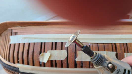
I then marked off the upper and lower areas to be cut using masking tape, and also marked the longitudinal areas to be removed. I then used this saw blade in a Dremel at fairly high speed to do most of the cutting:
1724695648908.png

The first opening went reasonably well (the saw kicks every so often, and has marked up neighboring frames, but I will fix that later):
1724695695726.png
The section I removed is shown to the right of the hole.
And here is the hole from above (not that it will normally be viewed this way):
1724695774858.png
Since this worked about as well as expected, I went ahead with the other openings:
1724695816301.png
What I've done here is to also cut through the forward magazine's support riders to better show the shells in the magazine, and in the aft magazine I've left the riders in place, showing a bit of the magazine but also the extreme supports necessary for the mortars.

From above you can see all three cutout areas:
1724695960339.png
I've got a lot of work to do to sand, shave, file and generally neaten up the openings, so things aren't quite as crude, as well as touch up any marred members, but that won't be hard.

The structure is surprisingly rigid and stable despite these large cutouts through main structural members, which is what I was hoping. It will only get stronger as additional beams and structure is added. I've done all these cutouts as well as outer planking early on (out of order to the instructions), so as to minimize damage to sawdust on inner finished areas. For me, this has been the way to go.
 
Back
Top