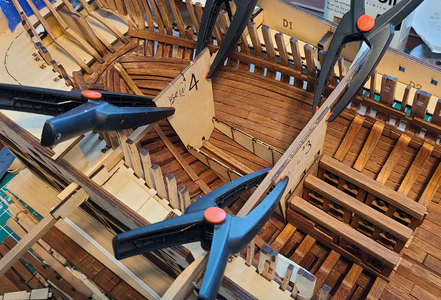
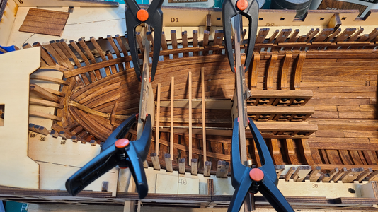
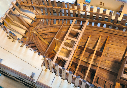
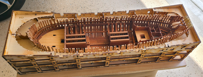
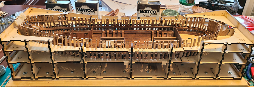
CAF Granado 1/48 PoF Bomb Vessel by Signet

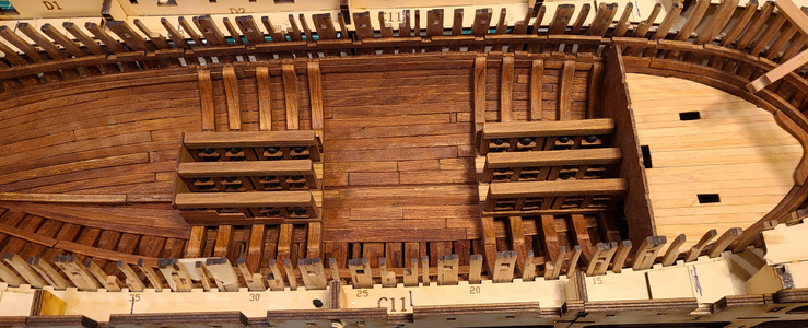
After rebuilding the mortar shell holders, I placed them and by trial-and-error (mostly error) sanded the slots of the cross beams to receive them and still fit tightly into their slots on the sides of the hull:
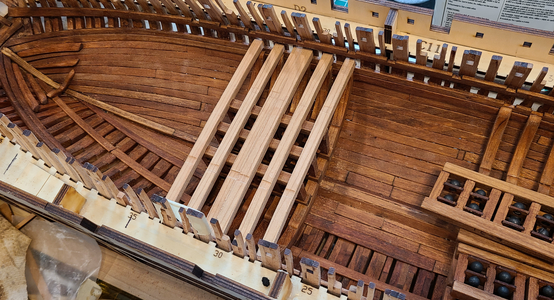
1719679015646.png
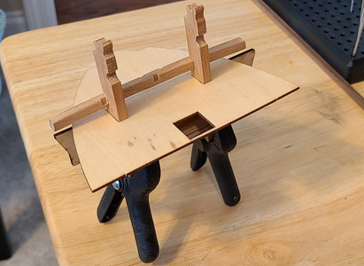
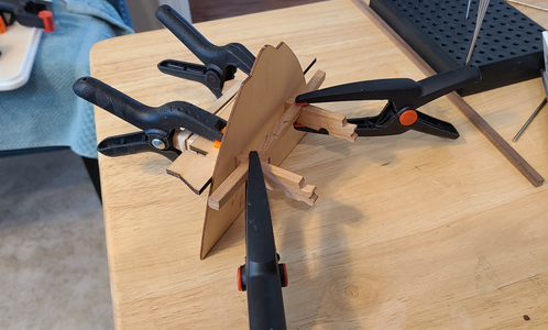
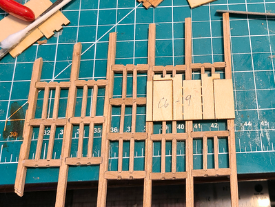
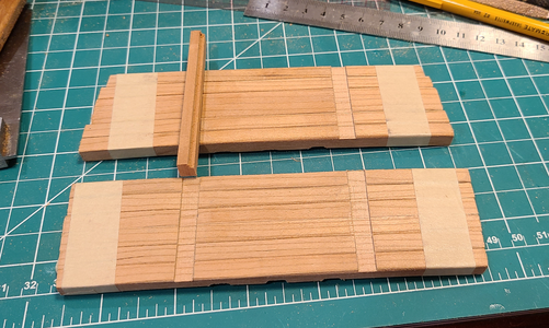
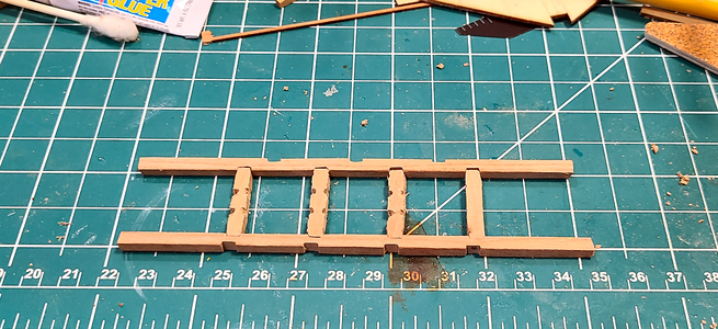
There was a slight variation in the cross beam thickness, which I thought might cause a problem, so hooked them together and sanded the tops to be flush with one another. This resulted in sanding some of the slots for the mortar supports on the top off a bit. But they were not wide enough to fit the 2 L-shaped supports anyhow, so took this opportunity to saw even and square slots for them. I first mounted the cross beams temporarily to their supports, then taped them together as a unit:
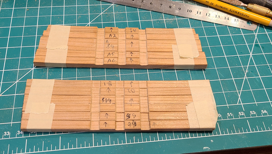
1719679270123.png1719679202234.png
After sawing the slots, they are square, of a uniform depth, and fit the L-shaped supports:
1719679361558.png
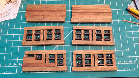
In the meantime, I put the planking on the side of the shell shelves areas:
1719679413353.png
I decided to fully plank the far side, which will not be visible, leave the fore shell shelves without planking, to hopefully be visible after completion, and the aft area I planked partially. We'll see how visible these areas area.

I forget if I mentioned previously that I had considered replacing half of the brass bombs included. The 50 included 0.25" scale to 12", which is a bit shy of the 13" size, but of course much too big for the 10" shells. However, the holes in the shell shelves are large enough to allow the scale 10" bombs to almost fall through, so decided to keep them as supplied with the kit.

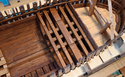
I next glued the assembled supports containing the shells into position. I didn't worry about them being square or upright; rather I fit the cross beams in their final position, not glued, to locate them. The most important thing is that they fit the cross beams so the height would be correct; I assumed they would end up vertical, or certainly close enough.
1719679763146.png
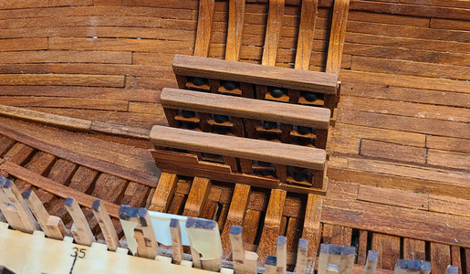
This photo shows the uprights glued in place:
1719679791186.png
But immediately, and before the glue has a chance to dry, the cross members are all fitted in place:
1719679827219.png
And after leaning quite heavily on this very strong assembly, I added weights to be sure they did not shift during glue curing:
1719679878799.png

That's it for today. Thanks to all those following, your likes and your comments. It helps make the build even more enjoyable. And as always, any ideas, suggestions, criticisms, etc. are welcome.
 
exclusive work, I love the colors of the model and the details, well done my friend
 
After rebuilding the mortar shell holders, I placed them and by trial-and-error (mostly error) sanded the slots of the cross beams to receive them and still fit tightly into their slots on the sides of the hull:
View attachment 456382
There was a slight variation in the cross beam thickness, which I thought might cause a problem, so hooked them together and sanded the tops to be flush with one another. This resulted in sanding some of the slots for the mortar supports on the top off a bit. But they were not wide enough to fit the 2 L-shaped supports anyhow, so took this opportunity to saw even and square slots for them. I first mounted the cross beams temporarily to their supports, then taped them together as a unit:
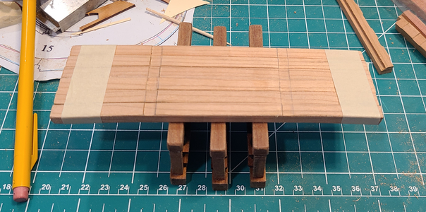
View attachment 456385View attachment 456383
After sawing the slots, they are square, of a uniform depth, and fit the L-shaped supports:
View attachment 456386
In the meantime, I put the planking on the side of the shell shelves areas:
View attachment 456387
I decided to fully plank the far side, which will not be visible, leave the fore shell shelves without planking, to hopefully be visible after completion, and the aft area I planked partially. We'll see how visible these areas area.

I forget if I mentioned previously that I had considered replacing half of the brass bombs included. The 50 included 0.25" scale to 12", which is a bit shy of the 13" size, but of course much too big for the 10" shells. However, the holes in the shell shelves are large enough to allow the scale 10" bombs to almost fall through, so decided to keep them as supplied with the kit.

I next glued the assembled supports containing the shells into position. I didn't worry about them being square or upright; rather I fit the cross beams in their final position, not glued, to locate them. The most important thing is that they fit the cross beams so the height would be correct; I assumed they would end up vertical, or certainly close enough.
View attachment 456388
This photo shows the uprights glued in place:
View attachment 456389
But immediately, and before the glue has a chance to dry, the cross members are all fitted in place:
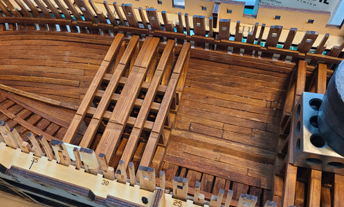
View attachment 456390
And after leaning quite heavily on this very strong assembly, I added weights to be sure they did not shift during glue curing:
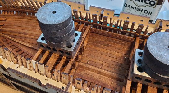
View attachment 456391

That's it for today. Thanks to all those following, your likes and your comments. It helps make the build even more enjoyable. And as always, any ideas, suggestions, criticisms, etc. are welcome.
Good morning. Very fine modelling indeed. Cheers Grant
 
WOW - you are very fast my friend - very good progress and also very good work
refering the height of the bulkhead I was also wondering about the sketch C4/2 - here I was also thinking several times about the correctness of Goodwins sketch
and also compared this detail with existing contemporary drawings

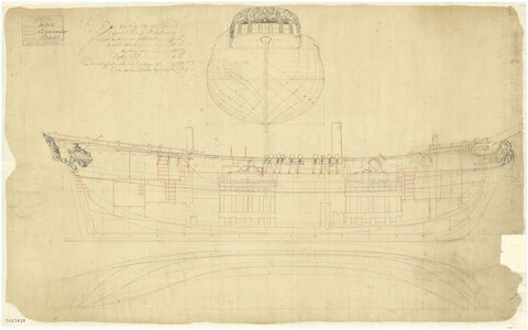
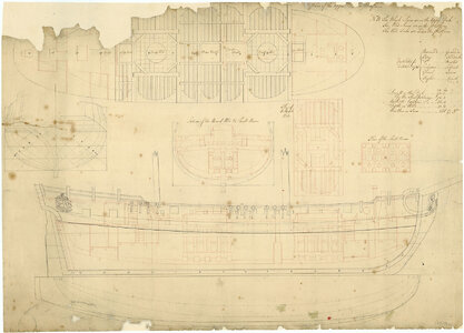
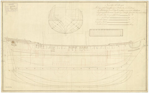
A) Here the Grenado / Granado - where no bulkhead is shown (like in Goodwin)

j0387.jpg

and
B) here other bomb vessels with the bulkhead going down to the keel and planking

j7658.jpg j0390.jpg

I concluded for myself, that both seems to be correct -
technically version B) was for me personally more logic in order to have a close room for the coal ........
 
I concluded for myself, that both seems to be correct -
I agree. There seems to always be quite a bit of variation, ship-to-ship, and even timeframe-to-timeframe. I myself take advantage that "The Captain decided to make changes...."
technically version B) was for me personally more logic in order to have a close room for the coal ........
I thought about the coal not being contained too, but assumed the large height of the floor rider would keep it in place, as there isn't that much coal - only for the the galley firehearth.
 
So, this is where I am at this point:
1720117693317.png

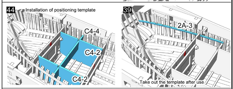
The lowest cross members are to be placed in the stern using templates #3 and #4, however I have a real problem using these templates. They don't always fit that well, for me, so take a while to finally get into place, and then I find it impossible to insert the additional template pieces, which then locate the cross beams. Therefore, for this step, I used only the center portions of templates #3 and #4, and carefully located these pieces centered, and in their correct fore-to-aft placement, by using shims, etc.:
1720117915578.png
This was much easier for me to do.
1720117962425.png
An advantage of this method is it is then easy to remove the template pieces allowing removal of the underneath template pieces, without cutting them up, per the instructions.

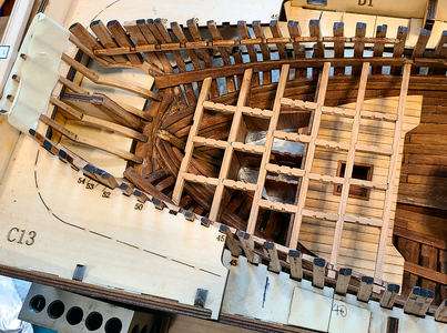
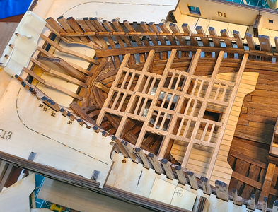
I found the next set of templates, intended to add the next set of beams, extremely difficult. No, impossible for me:
1720118208490.png
It was very difficult to assemble the template pieces between the main templates, as the main templates have to be extended out the entire way for the slots to be available to fit the added templates, yet they are locked almost completely when so extended. Piece C4-4 wasn't even long enough to reach the side to accurately locate the piece. I felt that there had to be an easier way, for me, but needed to understand at what height the 2A-3 above should be mounted.

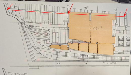
So, I copied the side plan in this area, and assembled the templates on it:

It really seemed to me that assembly of template C4-2 was done in a more difficult manner than necessary. The four beams that it partially sits on are already located, so why not just a rectangular template fitting over the beams?
1720118730580.png
This helped me understand the correct vertical location of this deck support, so simply used the locations existing on the assembled frame, in particular the 3 locations shown with arrows above, to locate these pieces:
1720118873933.png

The next step in the instructions shows using new templates to place just 2 cross beams for the next deck up:
1720118957160.png
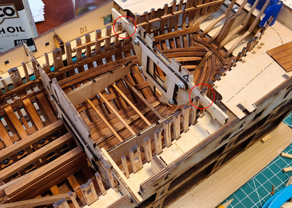
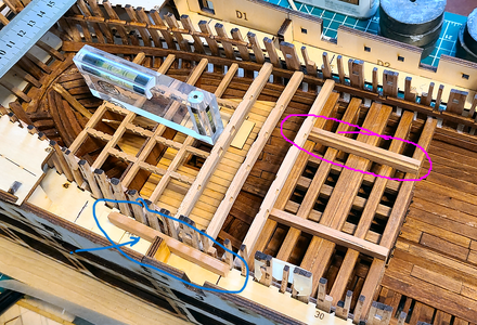
I again had problems with these templates. In fact, the previous step shown above, locating 2A-3 for the quarterdeck, now made it IMPOSSIBLE to place Template 4 in place. The photo below shows the installed quarterdeck supports interfering with placing template #4:
1720119301382.png
The circles indicate where the installed supports prevent the template from going into place. And it cannot be compressed, even without the center piece installed, enough to get it in. Template #4 is now officially worthless.

And this, if it could be done, would only result in 2 of the many required cross beams. Making it more difficult to plank the deck below it, as well as install the room partitions above that deck. I really felt that it would be better to simply add the lower deck, build and install the partitions, then let them locate the next set of beams.

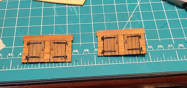
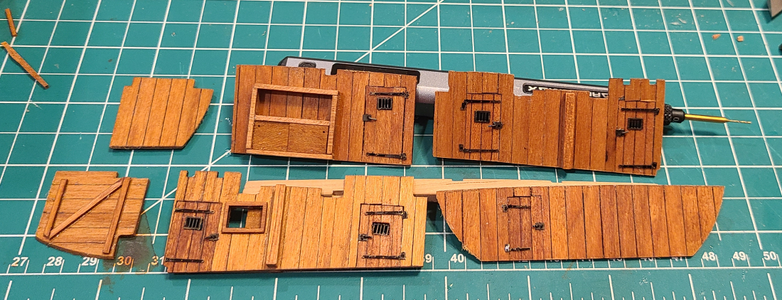
Before doing that, however, I thought I'd give a try with partitions at the bow, atop a deck I already had in place. But before that, I placed the doors and door hardware on the ends of the mortar magazines, prior to installation:
1720119461974.png
Yes, it's sloppy. Sorry, remember I'm Signet, not the brilliant builders that have other threads on this model. I have, however, tried to assemble the hinges the way they are intended, curling the ends of each part and putting pins into them, rather than just cutting them short like others have done. I felt the pin didn't add anything, but the curls do add a bit to the 3D quality, at least when viewing from a distance, between all the beams, as mine will be.

Before continuing on the bow partitions, I had to assemble the vertical windlass supports to its cross beam. To make sure it was parallel, and easy to later install after other parts are in place, I used the bow deck template as a template for locating the supports, and glued them in place:
1720119704990.png
I used a spacer to insure that the supports stayed parallel:
1720119723086.png
and clamped it all up for gluing:
1720119797910.png

I then temporarily fit the bow deck beams in place to locate the size and location of the partitions that go between. It was then that I found that I had installed this deck a bit too high, and rising quite a bit toward the bow, while it was supposed to be almost level. I had actually made the supports in the right location, but located it height-wise to match the outline, rather than the height. I considered removing the entire assembly, like a better builder would do, but reasoned that it might not be very noticeable after assembly - I'd just have to cut down the walls to fit.

This photo shows how much I had to remove from the first template and partition to fit properly, yet fit into the cross beams:
1720120027576.png
The foremost partition shows this as well:
1720120060068.png
Not great, I know. But it's where I am.

I now realized that I had a concern that the firehearth may not fit properly. I could shorten the stack, but at least the main firehearth had to fit, so used the modified templates and cross beams for a check:
1720120153415.png
It looks like it will fit, so I can probably go this way (with the modified height partitions). I wanted to be sure, though, so decided to continue on with the firehearth and finish it (up to a point, at least).

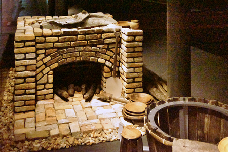
While I loved Uwe's incredible job on the firehearth for his model, my experience with firing ceramics told me that fire brick was quite different than normal building brick, using being a very light color. This is because they are made of sand, quartzite and other materials, rather than being primarily clay. The inside of a large brick oven, for example, might look like this:
1720120615727.png
And since the firehearth here is apparently made using mostly/all firebrick, it might look much like the one on the Mary Rose:
1720120735104.png
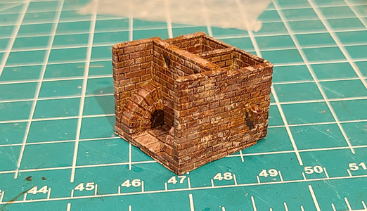
I decided to try my hand at achieving this appearance. My first attempt, while looking decent, was not very close to the firebrick I was seeking:
1720120805227.png
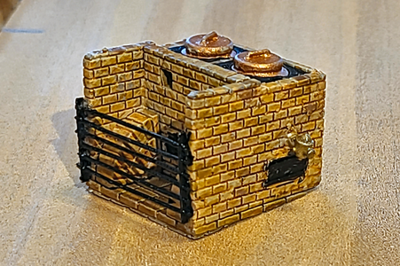
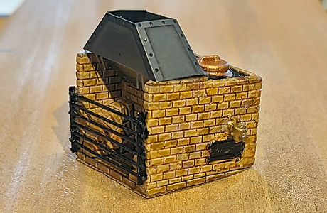
So I started over, and this is what I ended with:
1720120851251.png
1720122445181.png
This had the look I was going for, or at least it was close enough, so that is what I have. You may notice that I had to sand down the base of the firehearth, to both lower it a bit, and to make it vertical, due to my higher, sloped deck upon which it stands.

I've since gone back to the partitions, the first one anyhow, but don't have photos yet. I'll post them and more on my next post.
 
Last edited:
Always several ways to get to the same excellent end. It must be frustrating to not have the templates work like advertised but your ingenuity overcame this minor obstacle.

I do like the yellow firebrick. It is a very similar hue to the firebrick in the pizza oven I built in my last home! I'm assuming firebrick hasn't changed color too much over the centuries....

Thanks for sharing!!
 
Always several ways to get to the same excellent end. It must be frustrating to not have the templates work like advertised but your ingenuity overcame this minor obstacle.
Thanks. Some methods just make more sense to me.
I do like the yellow firebrick. It is a very similar hue to the firebrick in the pizza oven I built in my last home! I'm assuming firebrick hasn't changed color too much over the centuries....
I agree, and the photo from the Mary Rose seems to confirm this.

BTW, love your Bonhomme Richard cross section build! I really enjoyed that kit. Wish I had room for (and my wife would allow me to have) the full POF ship by the same manufacturer!
 
Bravo - I like your oven very much -> very good job
 
I finished off the lower level bow partitions and checked their fit with the cross beams to be mounted above them:
1720318957028.png
1720318977734.png
I moved the center partition between the galley and lobby aftward a bit to closer match Goodwin's drawings, then mounted the hardware to the doors. A number of them broke when handling, or fell to their death in the cat-fur-encrusted carpeting below my desk (a moment of silence for them, please.......).
1720319150135.png
I added some handles to the locks, a sliding panel on the boatswain's cabin's window, and gave the cook a cabinet for preparing and storing whatever he makes his broth out of (secret recipes from the Caribbean, no doubt). I know, at this level of size and illumination they look pretty bad, but in the dark area under the deck when seen though hull frames and deck structure, I think they'll look okay. They are not very close to the sizes intended, due to my deck error mentioned above, but they all fit properly beneath the cross beams, so will not cause a cascade of additional problems.

I'm not sure if it's safe to permanently glue these into place (without the beams above for now) or not, so will probably work elsewhere before comitting myself to that. I'll probably go back aft and see what I should do there.
 
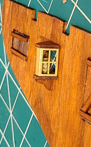
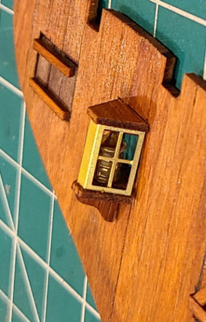
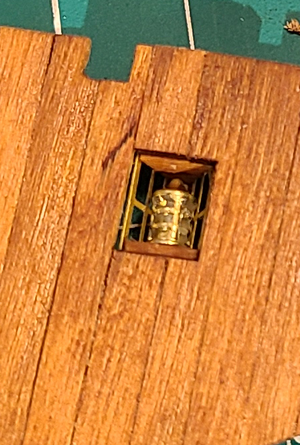
I will shortly be positioning, and probably gluing in place, the partition between the aft lobby and aft magazine/filling room, so decided to assemble the light assembly that provides light to the filling room, separating the room from the lamp (flame) with a glass and brass partition. I decided to leave the frame of the partition bright brass - maybe not accurate (but who's to say?), but the small detail will show up better that way. I also used a clear 3D printed lantern that my son made me for another project and use it inside the structure. It's not glued in place at this time, but I positioned it on the unfinished partition to get better pictures of it at this time:
1720578480166.png 1720578493343.png 1720578507823.png
1720578524793.png
You really can't see in the picture, as the brass reflects in the clear portions of the lantern, but the lantern is drilled at its base, representing a candle or other flame holder, with a yellow tip to represent the flame. Yeah, I know: great place for an LED. But I'm not doing that.

Going slowly on the aft partitions, as I'm attempting to confirm the fits and locations without the use of the templates, which I found impossible to use here. I'm trying to rationalize the location of the cross beams and carlings and such to fit properly with the partitions being added. Mostly trial and error, and planning the build in my head. 1720578957982.png
 
Continuing with the support structure and lower cabins at the aft of the ship, I found that the previously installed cross beam supports were not quite perpendicular with the keel, so trimmed the third one, which determines the location of the bulkhead before the powder and magazine rooms:
1720750417271.png
As I've said before, my building logs are usually about how to work around a problem (usually created by me), rather than the correct way to build things. Such is life.
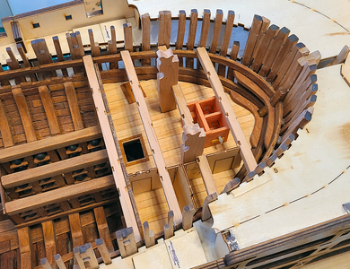
The partition mentioned above sits directly behind the third overhead beam for the officers' quarters, so I fit that beam in place, then fitted and glued the carlings connecting it and the third beam. Here the carlings are not yet glued to the 4th beam, as it hasn't yet been fitted to size for its location:
1720750795187.png
I've found it necessary to taper the ends of the carlings a bit, which is done easier than widening the slots, to get them to fit. If sanded their entire length to the correct width, the slots for the members between the carlings are sanded off. I've enlarged them a bit here.

Here the partition has been modified just a bit to get the carlings to properly fit through the slots, and be flush with the top of the partition:
1720750939609.png

In general, I like the construction, but have found that even after removing char on individual planks of partitions, the assembled partition is too wide, and slots don't match up. Which then requires more sanding of planks to get closer to the right dimension, then finally sanding the slots. I really think these pieces could have been designed and manufactured much more closely the the required dimension than they are. Sometimes, it's easier to just use strip planks, rather than pre-cut ones, as they can have the slots positioned as required.

Here the next beam has been fitted to size, and then assembled to the previous beam via the carlings:
1720751144769.png

Once the above is known to fit, the partition is glued in place, held to be vertical using a level and clamps.
1720751207915.png

Next the decking for the loading room area was completed and glued in place, being sure it is horizontal, and then the next partition is made and sized, using the intermediate wall template as a guide:
1720751317874.png
I had to reduce the height of the wall slightly to be sure it's flush with the first partition, as well as the second. I also found that the location where I had installed the four sleepers had them interfering with the aft wall, so had to remove them and shorten them some.
The first two cross beams are now able to be fitted in place, but not glued:
1720751395412.png
I will continue to assemble the beams with carlings, fitting them horizontally into place (not glued), and build each wall to fit into place in and around the beams and carlings. I am considering adding the 2x2mm strips in between the carlings shortly, to be sure the slots in the walls match up with them.

As I've said, this assembly procedure is bass-ackwards from the instructions, but I feel better about the fit that I will obtain by doing it in this way. I'm certain that just constructing all the parts and then assembling would result in interferences that would be harder to fix at that time.
 
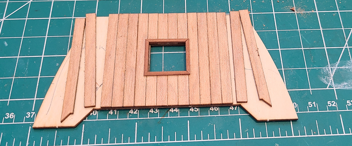
Working on the aft lower lobby planking next. I had a problem typical to the planking and partitions in this kit: The laser-cut planks are too wide. Not by much, and sure, I can sand the edges more to eliminate the problem, but depending on the shape, it's not always that easy. In general, the size of the partition and decking templates is extremely close. No, probably exact - it's my build that isn't so exact. And the laser-cut planks probably are too - as long as you sand the exact amount required off each edge. Tom I think said there was 0.3mm allowance for sanding, but I don't know if that's per side or total per plank. But I really don't want to sand that much off. For one thing, I like the slight laser char to be left, so it highlights the individual planks. And if I sand both sides that much, I guarantee they'll not be parallel any more. I'll give an illustration of the problem on this lobby planking:
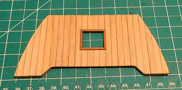
1721099806506.png
I had to sand the center four planks to get the hatch opening very close to what it should be. If not, it would have been a couple mm too wide. Fine.

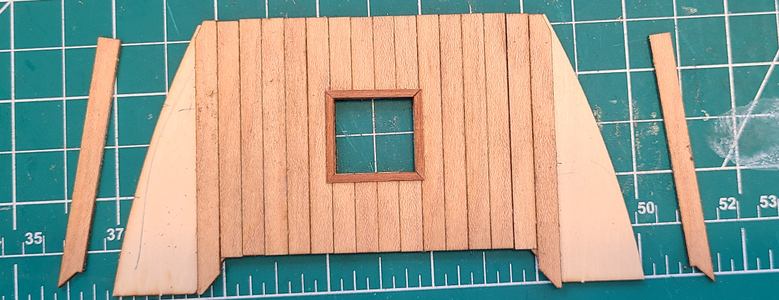
So I sanded the edges of the next ones a bit until I come to the 45 degree angle at the bottom. As you can see below, it's way off. Too wide:
1721100023339.png
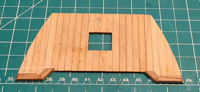
If I eliminate the rectangular planks, I can sand to the right location for the angle, but the top profile will be too short.
1721100164963.png
Sure, I know, sand each plank and dry-fit until it works. But with everything computer-generated and laser-cut, I don't think I should have to. To be honest, it would be easier to make the assembly out of the stripwood provided (thanks a lot for providing it!) rather than use the laser-cut pieces. But as I said above, I like to have a bit of the char there.

I ended up solving this (small) problem by using pieces from the the forward lower lobby planking, as I'd used stripwood for it. Inserting one piece on each side from it gave me the material I needed all around:
1721100343110.png
Even then, it's close to not having enough material at the top edge. I know this is really nit-picking. But not sanding these parts to the proper width, which is not specified, results in moving hatches, doors, etc. So it seems it could be done more accurately.

After constructing the planking assembly, I added some stripwood to the edges of the overhung areas, as I felt in real life they would need support, and not be hung from the walls:
1721100545826.png
1721100577651.png
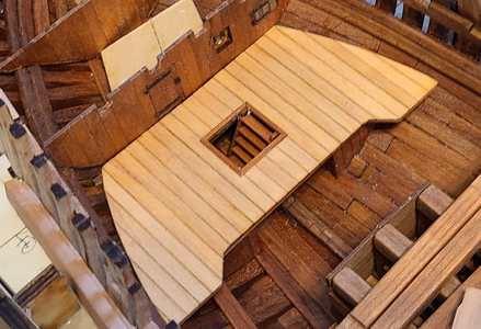
And after installation, I have:
1721100599442.png
(I have since reversed the stairs/ladder as it's supposed to go to the opposite side.)

Again, I am constructing the beam and carling assembly to fit in place /before/ making the partitions that go under them. As mentioned above, small errors in the width of the planks during assembly can mean that cut slots for beams and carlings are in the wrong place, so I prefer to have that assembly in place (dry fit, of course) when I make and fit the partitions.
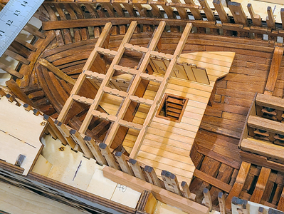
1721100768384.png
In each stage, I place the beam/carling assembly, level it, and add the next beam section, trimmed to the correct width:
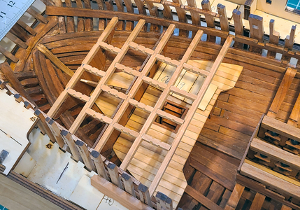
1721100823943.png
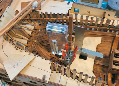
And with the furthest forward 5 of 6 beams in place, I check the cross beams above it for a good fit:
1721100953422.png
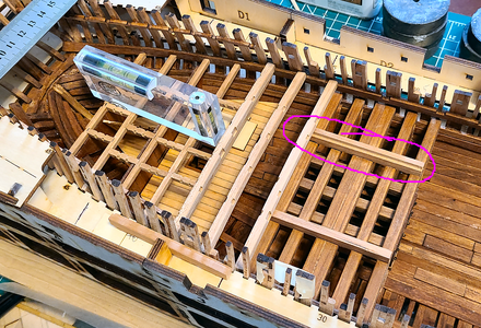
BTW, the circled piece above that supports the aft mortar structure is hand made by me from scrap from the piece that the other identical pieces came from. I lost one of those pieces over a week ago, and after searching EVERYWHERE for it, finally gave up and spent a good bit of today making one to match and fitting it in place.
HIDDEN PICTURE QUESTION: Can you find the 4th/lost piece that had eluded me all this time? I didn't find it until taking this picture! :rolleyes:
 
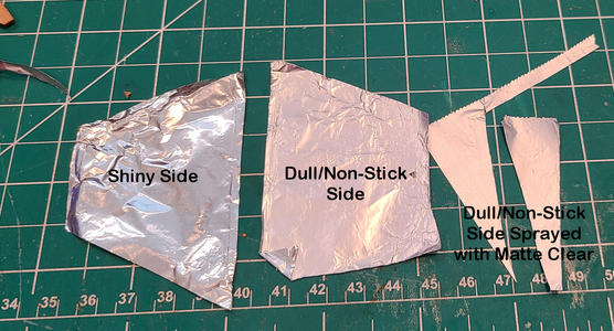
I decided to, like Uwe, add lead "flooring" in the Powder Room, Filling Room, and I also added it to the small Magazine Lobby to enter the Filling Room from the Platform Lobby. I didn't have any actual lead, so used a piece of non-stick aluminum foil. One side is extremely shiny, like standard aluminum foil, but the other is more dull. So I took a piece of it, and sprayed it with clear matte. The difference is visible:
1722027747228.png
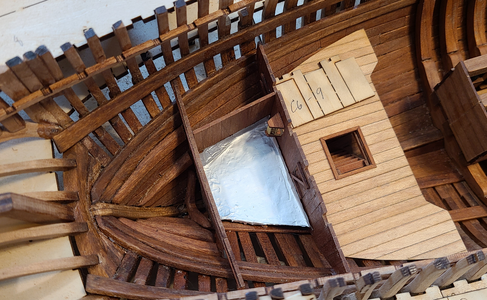
The "lead" flooring goes up the walls slightly:
1722027784518.png
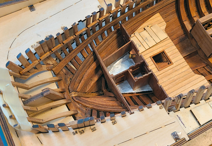
The Powder Room, Filling Room and Magazine Lobby have now been installed. Glued only to the walls, unfortunately, due to the aluminum flooring, but I think it will be secure enough:
1722027921719.png
1722027982740.png
You may notice that I reversed the swing of the door between the Magazine Lobby and the Filling Room. There was no way that the door could swing inward into the lobby with one or more people standing in it, awaiting entry to the Filling Room. The "lead" is not very impressive, but neither will it be very visible, as seen here:
1722028087012.png
and even less so after installing the small beams between the carlings (don't know what they're called):
1722028197416.png
The top half will be planked, and all of this deck will be covered by the Captain's deck, so not much of this will be seen.

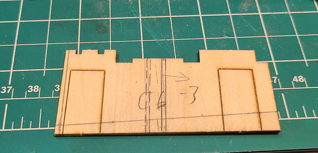
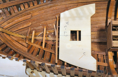
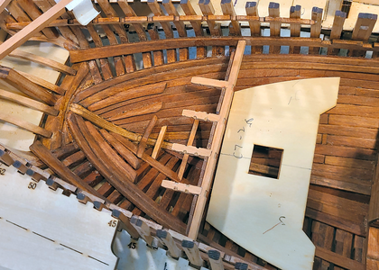
When making the partitions for the cabins, it is obvious that the template cutouts don't really match the beams and carlings:
1722028436824.png
At this point, I'm leaning toward making partitions of stripwood rather than the laser-cut pieces; less sanding is required, and I can add cutouts as required after assembly.

I have some big decisions to make now, which I'll discuss in the next post.
 
I decided to, like Uwe, add lead "flooring" in the Powder Room, Filling Room, and I also added it to the small Magazine Lobby to enter the Filling Room from the Platform Lobby. I didn't have any actual lead, so used a piece of non-stick aluminum foil. One side is extremely shiny, like standard aluminum foil, but the other is more dull. So I took a piece of it, and sprayed it with clear matte. The difference is visible:
View attachment 461249
The "lead" flooring goes up the walls slightly:
View attachment 461250
The Powder Room, Filling Room and Magazine Lobby have now been installed. Glued only to the walls, unfortunately, due to the aluminum flooring, but I think it will be secure enough:
View attachment 461251
View attachment 461252
You may notice that I reversed the swing of the door between the Magazine Lobby and the Filling Room. There was no way that the door could swing inward into the lobby with one or more people standing in it, awaiting entry to the Filling Room. The "lead" is not very impressive, but neither will it be very visible, as seen here:
View attachment 461253
and even less so after installing the small beams between the carlings (don't know what they're called):
View attachment 461258
The top half will be planked, and all of this deck will be covered by the Captain's deck, so not much of this will be seen.

When making the partitions for the cabins, it is obvious that the template cutouts don't really match the beams and carlings:
View attachment 461265
At this point, I'm leaning toward making partitions of stripwood rather than the laser-cut pieces; less sanding is required, and I can add cutouts as required after assembly.

I have some big decisions to make now, which I'll discuss in the next post.
Bravo - looking wonderful work
 
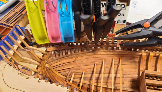
I'm hesitant to add too many more frames, beams and other structure, even though I've made them, because it's difficult to determine at this point what, if any, of the side of the hull structure I will be able to remove to make details visible. The Jig/Dock hides a lot of what I want to see, so I think it best to remove at least part of it.

I don't see where the Jig/Dock is really necessary any longer. The four templates were difficult or impossible for me to use for installing beams, so I abandoned that. But one thing that is not mentioned in the instructions, but is obvious from the plans, is that the top edge of the Jig is intended to match the top of all the frames. Mine did not. They varied, usually above the frame by as much as 1/8", a few slightly low. I felt it necessary to make them as close as possible to the height shown on the jig, so took the assembly to my garage.

Using a straight-edge from one side of the jig to the other, I sanded down, using a small 1/2" wide belt sander, the heights of the frames to more closely match the height and contour of the jig:
1722029068961.png
In this view, some of the aft cabin partitions are in place, done previously.

Thinking, I hope correctly, that I would no longer be needing most of the Jig/Dock, I removed (okay, destroyed) the sides of the dock:
1722029195244.png

My thinking at this point is that while this gives me good access to things, I cannot yet remove the hull from the dock, as I don't believe it's strong enough. Yet, I hate the idea of adding the temporary strips around the outside of the frames. I think I would like to next add at least some permanent planking and wales, after which I hope to be able to remove the model and determine what areas, if any, can be cut out. My thoughts are that if I add too much detail to the inside now, it will make cutting the cutouts much more difficult.

Thinking continues........
 
Back
Top