Good to know. I've used water-resistant PVA and didn't know there was a way to disassemble it.I use watertight PVA so I don't have another option than Acetone.
-

Win a Free Custom Engraved Brass Coin!!!
As a way to introduce our brass coins to the community, we will raffle off a free coin during the month of August. Follow link ABOVE for instructions for entering.
-

PRE-ORDER SHIPS IN SCALE TODAY!
The beloved Ships in Scale Magazine is back and charting a new course for 2026!
Discover new skills, new techniques, and new inspirations in every issue.
NOTE THAT OUR FIRST ISSUE WILL BE JAN/FEB 2026
You are using an out of date browser. It may not display this or other websites correctly.
You should upgrade or use an alternative browser.
You should upgrade or use an alternative browser.
CAF Granado 1/48 PoF Bomb Vessel by Signet
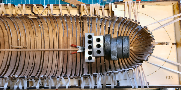
I thought I'd go ahead and place another set of frames, the ones under the next section of the keelson (under all the weights):
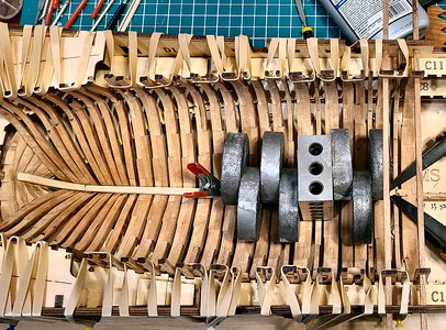
The sweep holes are lining up well, except for one which I modified a bit and noted about it. I had originally intended to assemble the entire keelson and glue it in place as one assembly, but some parts seem just a bit longer than the drawing shows, so I'm doing them one at a time. I know they all fit together well, and the final one ends against the rising bow/keel framing, and can be sanded for a good fit if necessary.
I hope my construction slows down a bit - this is going together entirely too fast. I was thinking I might spend as much as a year on Part 1, but no way. Of course, as I said above, I'm power sanding a lot, and haven't done the copper pins and such that others have done. I may add steel nails in the keelson, where it will be visible. I'm not sure yet. But, I certainly am enjoying the build, despite the minor problems I have had, most all my fault, of course.
And so on:
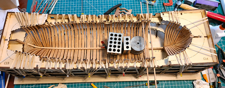
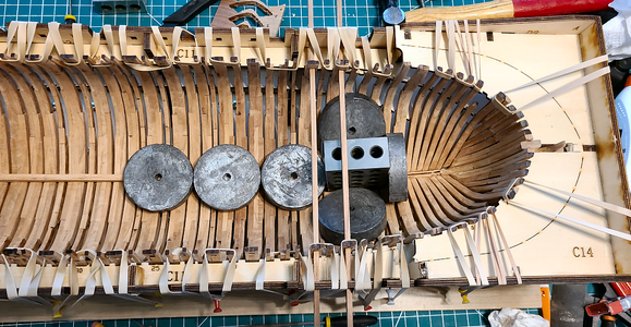
Yes, I do like my weights, especially where clamping is difficult.
And finally:
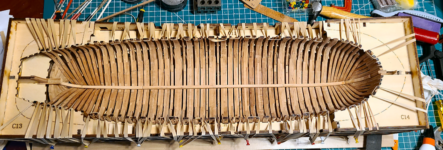
I'm now working on the pieces for the stern. Actually, the photo above shows one that will be added later, in place backwards just to determine fit. The corner stern pieces use 2 machined parts, and are very confusing, but I think they are correct.
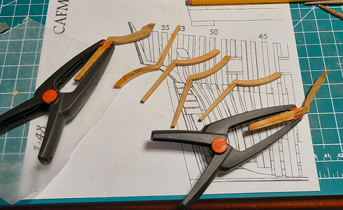
We'll see, after sanding.


Yes, I do like my weights, especially where clamping is difficult.

And finally:

I'm now working on the pieces for the stern. Actually, the photo above shows one that will be added later, in place backwards just to determine fit. The corner stern pieces use 2 machined parts, and are very confusing, but I think they are correct.

We'll see, after sanding.
PROBLEM: I thought I'd read where there was a problem with the four locating templates (beginning of build Part #2) and the gun port sills, but couldn't find it. I did my own investigation, and strongly feel that the port sills cannot be put into place, especially the upper ones, for the templates to work. I emailed Tom concerning this just this afternoon, hadn't yet received an answer, so looked again through all my links.
These are the sills in question:
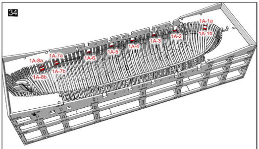
While I couldn't find anything mentioned in Uwe's or Keef's build, I finally found what I was looking for in Adiefenbach's Granado Build. He found the same problem: If the sills (parts 1A-1 to -8) are installed per the drawing in Part 1, the templates will not work in Part 2. In fact, I don't think template #4 will even be able to be fit in place. I had already glued the lower sill at the cabin window (1A-8b), but no template goes through there, so don't think it is a problem.
SOLUTION: The above instruction should be eliminated from Part 1, and done after considerable work on Part 2.
These are the sills in question:

While I couldn't find anything mentioned in Uwe's or Keef's build, I finally found what I was looking for in Adiefenbach's Granado Build. He found the same problem: If the sills (parts 1A-1 to -8) are installed per the drawing in Part 1, the templates will not work in Part 2. In fact, I don't think template #4 will even be able to be fit in place. I had already glued the lower sill at the cabin window (1A-8b), but no template goes through there, so don't think it is a problem.
SOLUTION: The above instruction should be eliminated from Part 1, and done after considerable work on Part 2.
I've started working on Part 2 of the kit, and am running into a problem:
PROBLEM: The listed part numbers appear to be reversed on the first longitudinal inside strips/wales. The first instruction in question is this:
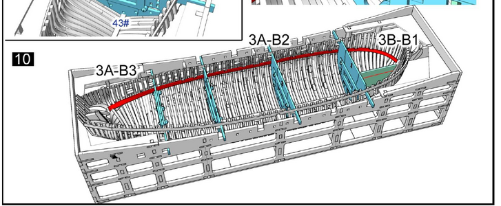
Here are the parts in the sheets identified by those numbers:
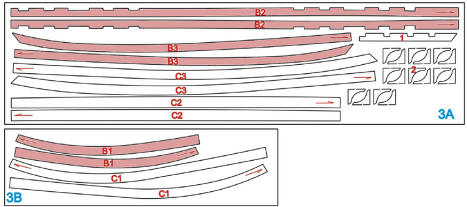
Those parts do NOT seem to match the drawing, which shows the parts in place:

The parts identified above match the LOWER of the two rails in the drawing, not the UPPER one which the instructions call for.
Likewise, the next instruction calls for installation of the Lower rails:
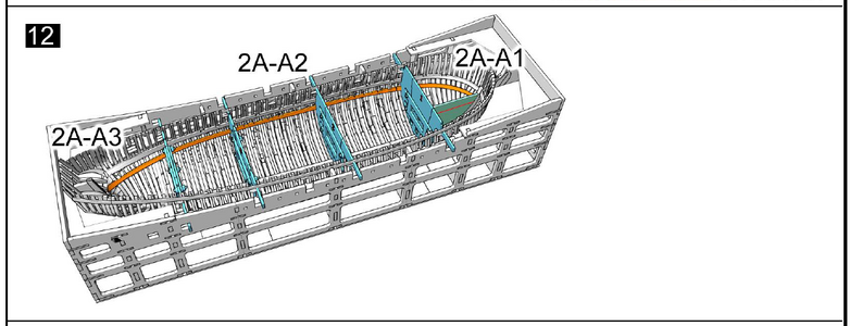
It is obviously shown installed BELOW the one installed in step 10. Here are the pieces that step 12 calls for:

Those parts, intended for the TOP rail, match the drawing shown for the BOTTOM rail (see the photo above). Basically, I have placed the pieces just above the parts shown on the drawing that best match the pieces. And they are reversed from the numbers shown on the instructions.
SOLUTION(?): Reverse the part numbers used in steps 10 and 12? Or am I misunderstanding something?
PROBLEM: In addition to the above, there is no clear point for the 3 strips to start and end. I can start at one end or the other, but will all the slots end up in the right place? The upper strip shows a joint about frame 10 or so, so should I scale off of that? The other joint isn't located, and none are located on the bottom strip.
SOLUTION: The only thing I can think of is to use the drawing to locate the center strips in what appears to be the most accurate horizontal position, matching the drawing, and add the other pieces to each end. That's a bit concerning, especially since the center top strip's notches don't match the drawing, and neither matches the part sheet drawing above.
PROBLEM: The listed part numbers appear to be reversed on the first longitudinal inside strips/wales. The first instruction in question is this:

Here are the parts in the sheets identified by those numbers:

Those parts do NOT seem to match the drawing, which shows the parts in place:

The parts identified above match the LOWER of the two rails in the drawing, not the UPPER one which the instructions call for.
Likewise, the next instruction calls for installation of the Lower rails:

It is obviously shown installed BELOW the one installed in step 10. Here are the pieces that step 12 calls for:

Those parts, intended for the TOP rail, match the drawing shown for the BOTTOM rail (see the photo above). Basically, I have placed the pieces just above the parts shown on the drawing that best match the pieces. And they are reversed from the numbers shown on the instructions.
SOLUTION(?): Reverse the part numbers used in steps 10 and 12? Or am I misunderstanding something?
PROBLEM: In addition to the above, there is no clear point for the 3 strips to start and end. I can start at one end or the other, but will all the slots end up in the right place? The upper strip shows a joint about frame 10 or so, so should I scale off of that? The other joint isn't located, and none are located on the bottom strip.
SOLUTION: The only thing I can think of is to use the drawing to locate the center strips in what appears to be the most accurate horizontal position, matching the drawing, and add the other pieces to each end. That's a bit concerning, especially since the center top strip's notches don't match the drawing, and neither matches the part sheet drawing above.
PROBLEM: While related to the above problem, this is a separate one, and to be honest, very concerning. I assembled the templates today, and put them in place, marking the A and B locations as carefully as I could, as outlined in the instructions. This is typical in how A and B are located:
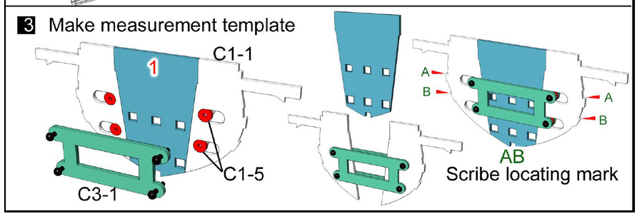
The instructions clearly show the bottom of the top strip to be at level A:
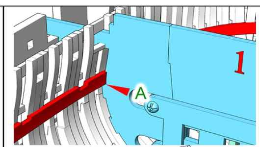
and the bottom of the lower strip to be at Level B (although somewhat less clearly):

I could not determine exactly what height these strips should be in areas other than the 4 templates, so was comparing the drawing with the template, and found what I think is a huge error. After more ShipsOfSale.com searches for this problem,
During the process of solving the previous problem (if in fact I have solved it), I found this post by Uwe in tedboat's Granado build, giving an entirely different location for the lower strip: rather than the bottom being at the B height, the TOP needs to be at the top of the notch ABOVE the B point!
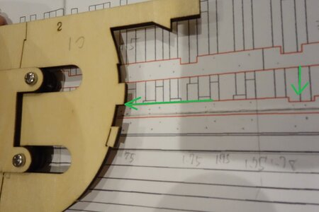
This is a huge error, IMHO, one that could ruin the entire build. Well, okay, it's only 2-3mm, but that's 2-3mm less room for everything below that point, and I think it would really mess things up.
SOLUTION(?): I don't know. I can use Uwe's instructions at the four templates, which appear to raise the lower strip about 2mm. Do I also raise the point of the bow 2mm? Or I guess take measurements off the drawing? The templates are good for height at 4 places, but there's nothing else to determine these heights, which are quite critical. I wonder: Does a strip of inside planking go between these two strips? If so, that might be a good way to locate one from the other, at least. I don't know, this is frustrating. The most comprehensive builds of this model don't have any of these questions mentioned, I believe.
I think it's time to sit still and study, rather than build. I'm good at that, at least.

The instructions clearly show the bottom of the top strip to be at level A:

and the bottom of the lower strip to be at Level B (although somewhat less clearly):

I could not determine exactly what height these strips should be in areas other than the 4 templates, so was comparing the drawing with the template, and found what I think is a huge error. After more ShipsOfSale.com searches for this problem,
During the process of solving the previous problem (if in fact I have solved it), I found this post by Uwe in tedboat's Granado build, giving an entirely different location for the lower strip: rather than the bottom being at the B height, the TOP needs to be at the top of the notch ABOVE the B point!

This is a huge error, IMHO, one that could ruin the entire build. Well, okay, it's only 2-3mm, but that's 2-3mm less room for everything below that point, and I think it would really mess things up.
SOLUTION(?): I don't know. I can use Uwe's instructions at the four templates, which appear to raise the lower strip about 2mm. Do I also raise the point of the bow 2mm? Or I guess take measurements off the drawing? The templates are good for height at 4 places, but there's nothing else to determine these heights, which are quite critical. I wonder: Does a strip of inside planking go between these two strips? If so, that might be a good way to locate one from the other, at least. I don't know, this is frustrating. The most comprehensive builds of this model don't have any of these questions mentioned, I believe.
I think it's time to sit still and study, rather than build. I'm good at that, at least.
Good morning. My next ship will be an attempt at a POF. reading through this I'm not sure I am ready for such a project. Your frame work looks brilliant and i, sure these problems will find a solution. Cheers GrantPROBLEM: While related to the above problem, this is a separate one, and to be honest, very concerning. I assembled the templates today, and put them in place, marking the A and B locations as carefully as I could, as outlined in the instructions. This is typical in how A and B are located:
View attachment 449941
The instructions clearly show the bottom of the top strip to be at level A:
View attachment 449942
and the bottom of the lower strip to be at Level B (although somewhat less clearly):
View attachment 449943
I could not determine exactly what height these strips should be in areas other than the 4 templates, so was comparing the drawing with the template, and found what I think is a huge error. After more ShipsOfSale.com searches for this problem,
During the process of solving the previous problem (if in fact I have solved it), I found this post by Uwe in tedboat's Granado build, giving an entirely different location for the lower strip: rather than the bottom being at the B height, the TOP needs to be at the top of the notch ABOVE the B point!
View attachment 449961
This is a huge error, IMHO, one that could ruin the entire build. Well, okay, it's only 2-3mm, but that's 2-3mm less room for everything below that point, and I think it would really mess things up.
SOLUTION(?): I don't know. I can use Uwe's instructions at the four templates, which appear to raise the lower strip about 2mm. Do I also raise the point of the bow 2mm? Or I guess take measurements off the drawing? The templates are good for height at 4 places, but there's nothing else to determine these heights, which are quite critical. I wonder: Does a strip of inside planking go between these two strips? If so, that might be a good way to locate one from the other, at least. I don't know, this is frustrating. The most comprehensive builds of this model don't have any of these questions mentioned, I believe.
I think it's time to sit still and study, rather than build. I'm good at that, at least.
I felt exactly the same way, as I've never built a POF until now, but it's actually gone quite easily. In fact, it has taken much less time than I thought it would (but then I have been using power sanding for most shaping, and I'm not doing the brass and iron pins that others are). I do have some questions on the above, and want to research and think about it quite a bit, because I know not doing something right at this stage will have horrible repercussions later!Good morning. My next ship will be an attempt at a POF. reading through this I'm not sure I am ready for such a project.
Thanks very much. If you really want to see brilliant, I refer you to Uwe's build, but I think it looks okay so far.Your frame work looks brilliant and i, sure these problems will find a solution. Cheers Grant
I decided to go ahead and mount the top set of rails that support cross beams, at the A position shown on the plans and templates. I hate going back and enlarging mounting slots for beams after they are glued in place, so the first thing I did, while cleaning up these pieces, is check the slots against the beam thicknesses that will be mounted in them:
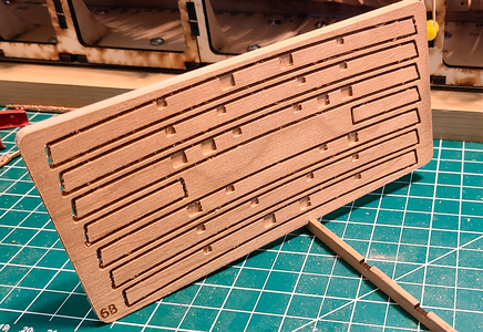
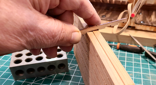
In most cases, the slots were a bit narrow, so the first order of business is to widen them for a good fit.
The first method I tried in mounting these rails was to place them, using the templates, clamp them in place, then glue blocks underneath with Fixo-Gum to provide the proper position for the piece:
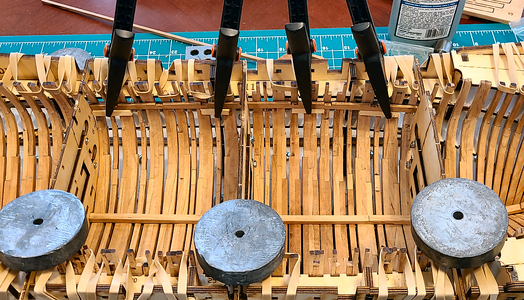
The problem here, for me at least, is that while the templates locate the pieces well, they can't easily be glued in position at that time, unless maybe dripping CA glue in from above. I needed to remove the templates to glue the piece properly, at which time I lose their location. So the blocks underneath help with that. After removing the templates, the blocks remain, so glue is applied for the strip:
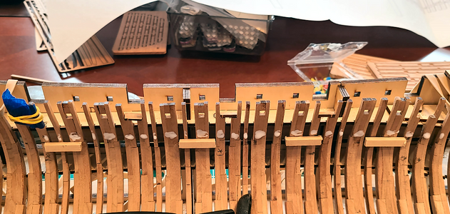
Important Note: The cross pieces in the gunport slots cannot be glued in place prior to this as shown in the Part 1 instructions because that creates an error in using the four Templates. But I positioned them temporarily in their locations prior to gluing these strips on to maintain the proper spacing of the frames at these locations, because gluing the strips on determines their locations.
and then the strip is positioned and clamped:
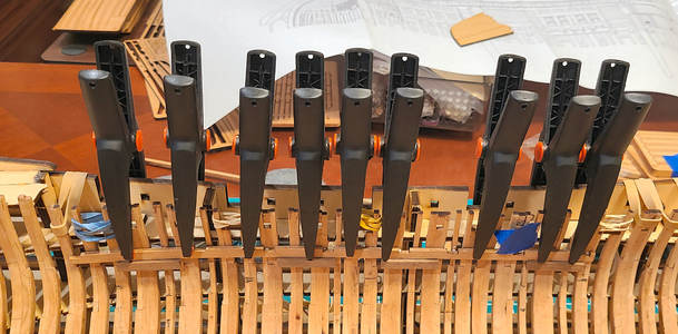
This worked okay, but even after letting the Fixo-Gum adhered blocks cure overnight, they didn't hold as well as I liked to position the pieces.
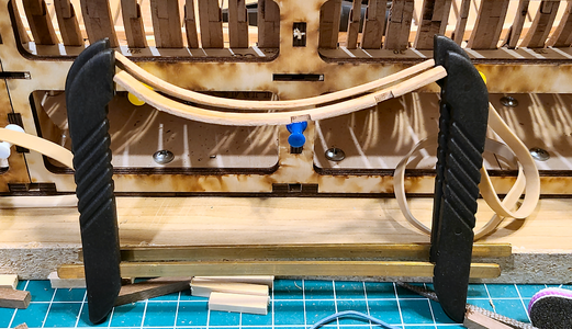
In the meantime, I curved the bow portions of this A strip using the soldering-iron-like plank bender on hot water moistened strips. That worked pretty well. I found later moistening for small changes un-did the bend, so don't advise that. Once they were bent okay, I used this method to keep them bent until they were used:
Again, I needed to widen the slots in these pieces to be sure the cross beams would fit, since they enter at an angle:
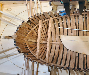
When gluing the aft portions of these riders in place, I experimented with other means of keeping them located:
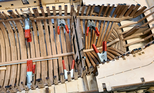
in this case, using small clamps below them, once located by the templates.
And a combination of clamps to keep the piece in place:
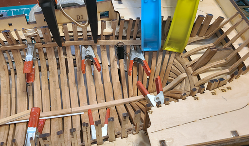
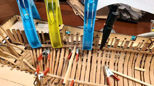
Because of the twisting and bending here, I used Uwe's combination of every so many frames being CA-glued in place, to help hold, with the rest PVA-glued to bridge any gaps.
The curved bow pieces hold in place pretty well by themselves, because they're positioned and really tightly held at each end, so require minimal clamps:
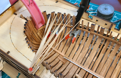
The rubber bands are to help insure contact with the strip, although I had to change the above after the photo to to properly space the frames.
After completion, the result is a more rigid hull structure with rib spacing held better:
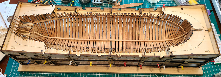
Also after completion, I saw that the aft end of these strips end at a higher level. I mistook the dock height at that place for the beginning of the curve. But they're glued with both CA and PVA, so more difficult to change, and as far as I can tell, the exact height of them at this point should not matter much. Overall, the installed strips seem to vary from the drawing, but are pretty close to the template locations. I hope they're work. I'm prepared to trim or shim to get the required height of the cross members.
I'm having second thoughts about putting the B strip in next, per the instructions. With everything so critical, and no clear answer about where the strip should be locate, I may be better to begin working on the ceiling planking and work up from the mortar structures. We'll see.


In most cases, the slots were a bit narrow, so the first order of business is to widen them for a good fit.
The first method I tried in mounting these rails was to place them, using the templates, clamp them in place, then glue blocks underneath with Fixo-Gum to provide the proper position for the piece:

The problem here, for me at least, is that while the templates locate the pieces well, they can't easily be glued in position at that time, unless maybe dripping CA glue in from above. I needed to remove the templates to glue the piece properly, at which time I lose their location. So the blocks underneath help with that. After removing the templates, the blocks remain, so glue is applied for the strip:

Important Note: The cross pieces in the gunport slots cannot be glued in place prior to this as shown in the Part 1 instructions because that creates an error in using the four Templates. But I positioned them temporarily in their locations prior to gluing these strips on to maintain the proper spacing of the frames at these locations, because gluing the strips on determines their locations.
and then the strip is positioned and clamped:

This worked okay, but even after letting the Fixo-Gum adhered blocks cure overnight, they didn't hold as well as I liked to position the pieces.
In the meantime, I curved the bow portions of this A strip using the soldering-iron-like plank bender on hot water moistened strips. That worked pretty well. I found later moistening for small changes un-did the bend, so don't advise that. Once they were bent okay, I used this method to keep them bent until they were used:

Again, I needed to widen the slots in these pieces to be sure the cross beams would fit, since they enter at an angle:

When gluing the aft portions of these riders in place, I experimented with other means of keeping them located:

in this case, using small clamps below them, once located by the templates.
And a combination of clamps to keep the piece in place:


Because of the twisting and bending here, I used Uwe's combination of every so many frames being CA-glued in place, to help hold, with the rest PVA-glued to bridge any gaps.
The curved bow pieces hold in place pretty well by themselves, because they're positioned and really tightly held at each end, so require minimal clamps:

The rubber bands are to help insure contact with the strip, although I had to change the above after the photo to to properly space the frames.
After completion, the result is a more rigid hull structure with rib spacing held better:

Also after completion, I saw that the aft end of these strips end at a higher level. I mistook the dock height at that place for the beginning of the curve. But they're glued with both CA and PVA, so more difficult to change, and as far as I can tell, the exact height of them at this point should not matter much. Overall, the installed strips seem to vary from the drawing, but are pretty close to the template locations. I hope they're work. I'm prepared to trim or shim to get the required height of the cross members.
I'm having second thoughts about putting the B strip in next, per the instructions. With everything so critical, and no clear answer about where the strip should be locate, I may be better to begin working on the ceiling planking and work up from the mortar structures. We'll see.
 , now to decide where to start planking the ceiling. You'd think that would be easy. Maybe it is for most people. But I'm uncertain exactly where the first row of planking starts and stops.
The instructions show it this way:
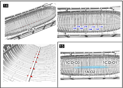
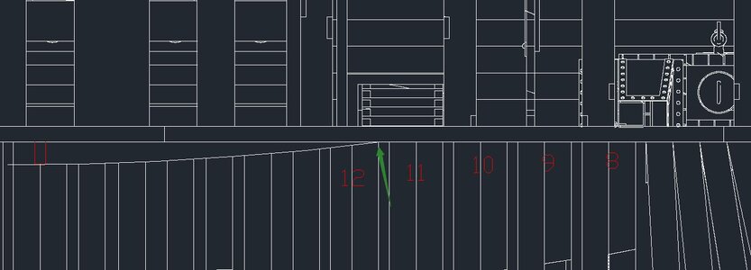
The location of the little triangle 2A-1 parts are shown exactly (okay, very close), on the specified ribs #17 to #34. But the first row of planking 'O' is not shown exactly where it should start and end. I can assume that the center part O2 is centered on the little 2A-1 triangles, in particular centering it between the 2nd and 5th triangles. But that's a big assumption. I can probably be within a frame distance or so based on the diagram, but that doesn't really come out right.
Why does it matter? Well, the O plank is the guide for all the other planks, which will be centered on each previous plank. So if 'O' is 1 inch too far aft, the whole planking structure will move 1" too far aft. I think this is why some builders of this model have found one end or the other thinning way down, where the gap should be fairly constant.
Here are the little 2A-1 parts in place:
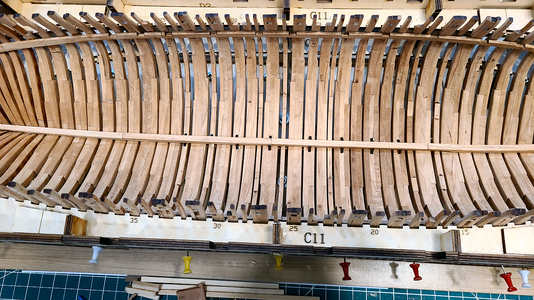
and the pieces of the first 'O' planking row:
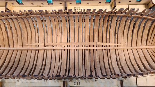 The plank pieces are shown approximately centered, which might not be far off.
I thought maybe layout out all the planks in order might make it obvious where to start:

It didn't. It did seem to show some planks that might not fit well to their neighbors, but hopefully that won't be the case. I (think) I can see that some planks will have to be trimmed/sanded a bit to fit at the end(s), but of course that results in the question of which end to start from? The bow or the stern? It seems like it would be the bow, but I really can't tell.
But again, it's obvious to me that if I don't start with plank 'O' in the right place, plank D will not end up in the right place, and that is critical. Anyone have any ideas?
And aligning the aft end of all planks as accurately as I can:

It really looks like planks 'I' and 'K' are too long, in relation to the the others. Since they can, and may, be trimmed, that's not too much of a problem, except again, do I start at the bow or the stern, as the profile of these will be different each way.

It really looks like planks 'I' and 'K' are too long, in relation to the the others. Since they can, and may, be trimmed, that's not too much of a problem, except again, do I start at the bow or the stern, as the profile of these will be different each way.
O-kay, I decided that I might want to work from the top down on inner planking rather than the bottom up, and wasn't satisfied with the location of the aft 'B' piece; I'd mentioned that above, that I'd worked to the wrong position. So I removed them:
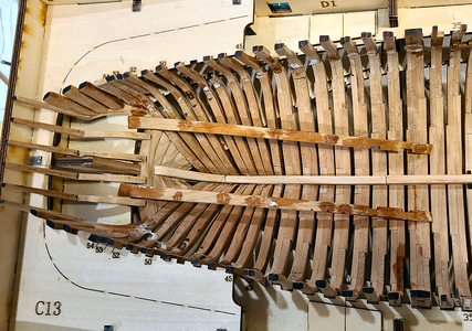
The PVA glue removed fairly easily with water, and the CA glue came loose as well. Afterwards, I cleaned up the glued areas on the hull and strips:
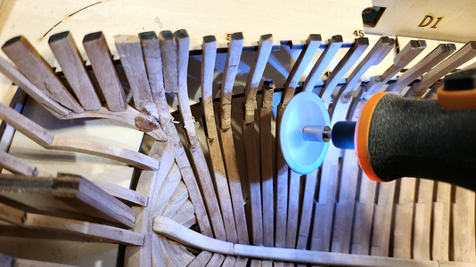
Then repositioned the strips:
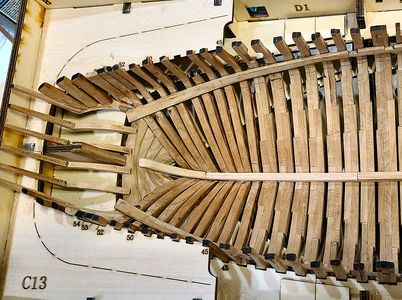
They weren't moved that much, but hopefully will allow more accurate planking positioning. I was now quite happy with the locations of the 'A' strips; they matched the templates, drawings, etc. and I feel would form a good basis for continued inside planking.
Concerning positioning of the 'B' strips mentioned above, I got conflicting information concerning the vertical location, and the templates resulted in inconsistent positioning as well. So I measured the distance between the 'A' and 'B' strips on the side view drawing, and ended simply spacing down from the 'A' strips, rather than marking new locations using the templates. I reasoned that the 'B' strip should be almost a constant distance from the 'A', so used some scrap strips 9.5mm wide to do the spacing between them, adding an extra 1mm at template location 1. I glued these in place using rubber cement, to assist in locating the 'B' strip:
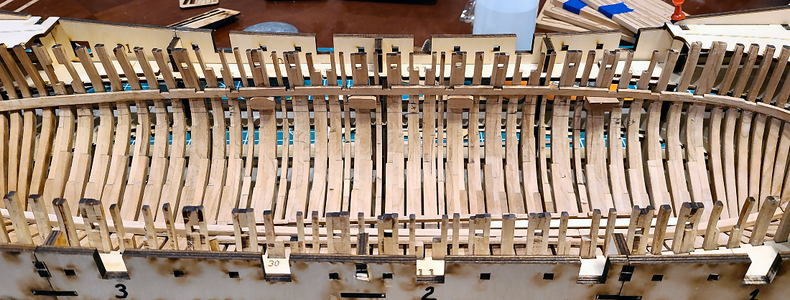
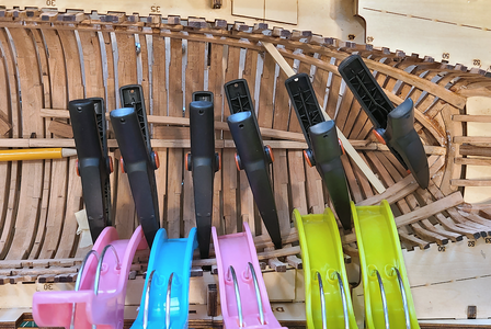
First step was locating the center 'B' strips on each side, using my new wide-opening clamps:
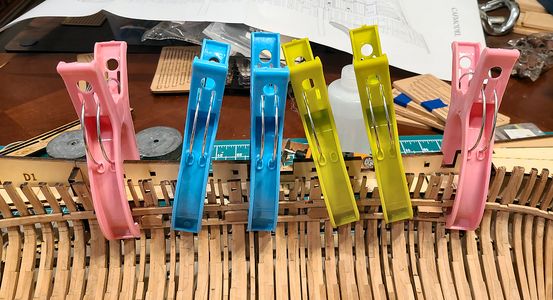
Jealous of the clamp's colors, aren't you? Well, they actually worked pretty well for these strips, opening as far as they do.
Then I continued on to the aft 'B' strips, using spacers as well:
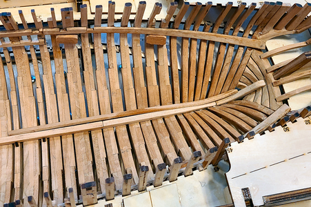
I used a heating soldering-iron style plank bender, but had trouble keeping the twist needed for these planks. So I invented the Signet Torsional Clamping System®":
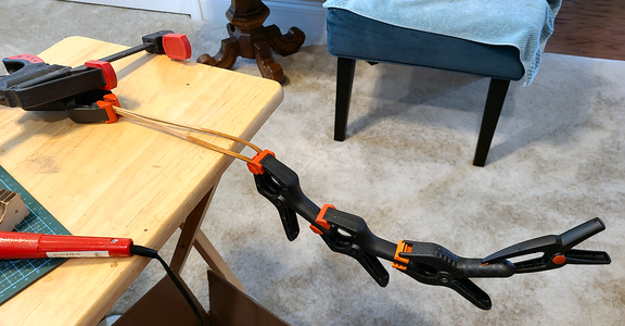
This helped fit these strips in place:
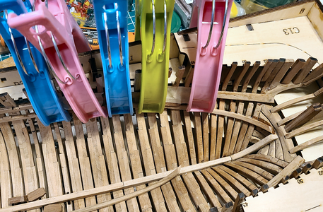
I also used blocks to help space the fore 'B' strips:
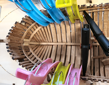
That completes the 'B' strips, as accurately as I can make them. Hopefully, they will work with the cross supports over the mortar mounts, which is their main purpose.

The PVA glue removed fairly easily with water, and the CA glue came loose as well. Afterwards, I cleaned up the glued areas on the hull and strips:

Then repositioned the strips:

They weren't moved that much, but hopefully will allow more accurate planking positioning. I was now quite happy with the locations of the 'A' strips; they matched the templates, drawings, etc. and I feel would form a good basis for continued inside planking.
Concerning positioning of the 'B' strips mentioned above, I got conflicting information concerning the vertical location, and the templates resulted in inconsistent positioning as well. So I measured the distance between the 'A' and 'B' strips on the side view drawing, and ended simply spacing down from the 'A' strips, rather than marking new locations using the templates. I reasoned that the 'B' strip should be almost a constant distance from the 'A', so used some scrap strips 9.5mm wide to do the spacing between them, adding an extra 1mm at template location 1. I glued these in place using rubber cement, to assist in locating the 'B' strip:

First step was locating the center 'B' strips on each side, using my new wide-opening clamps:

Jealous of the clamp's colors, aren't you? Well, they actually worked pretty well for these strips, opening as far as they do.
Then I continued on to the aft 'B' strips, using spacers as well:

I used a heating soldering-iron style plank bender, but had trouble keeping the twist needed for these planks. So I invented the Signet Torsional Clamping System®":

This helped fit these strips in place:

I also used blocks to help space the fore 'B' strips:

That completes the 'B' strips, as accurately as I can make them. Hopefully, they will work with the cross supports over the mortar mounts, which is their main purpose.
Good morning. Wow a lot of work and starting to look like a ship. You are doing a fine job on this POF. Cheers GrantContinuing on with strip 'C', the patented Signet Torsional Clamping System® is used once again:
View attachment 451651
View attachment 451652
View attachment 451653
View attachment 451654
I'm feeling most of the strips are created a bit more curved than necessary, but that's probably just me. Most require more bending on each end to fit tight against their neighbor.
View attachment 451655
Thanks very much, Grant. Yeah, it's starting to look ship-like. ;-)Good morning. Wow a lot of work and starting to look like a ship. You are doing a fine job on this POF. Cheers Grant
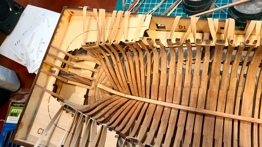
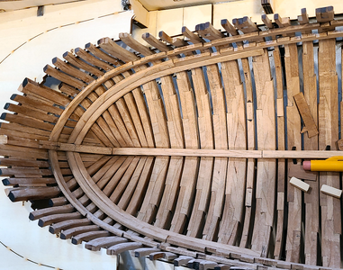
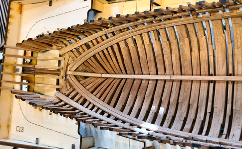
I've decided to do the inner planking from the top down to the keel, rather than the other way 'round as the instructions state. I can't visualize everything working out right to the 2mm thick inner supports if I start at the bottom, and think that the planking nearer the waterline will be much more visible than that near the keel. Also, the instructions say to adjust planks D for final fit, after working up from the keel. But I feel that I should be able to adjust plank 'M' (next to the last lower plank) or thereabouts to do the same thing. This may come back to bite me, but we'll see.
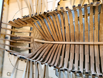
As mentioned above, most of the pieces being put into place appear more curved than necessary as they are placed:
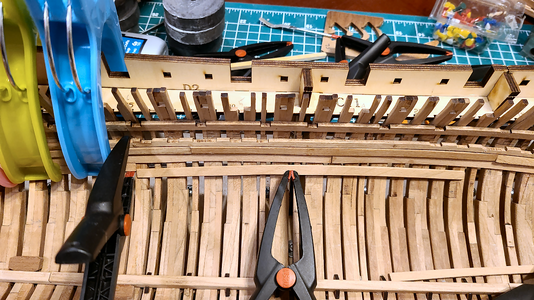
This is probably the least curved, but you get the idea. Near the center of the model, straight strips would be preferred to curved ones like this, since a single clamping in the center would hold the strip to the proper curve, while this way each end needs clamping.
I've been proceeding from aft toward bow in placing the pieces. The aft piece is pretty easy to place, as it fits well, and the middle piece(s) are easiest to fit as well as to clamp:
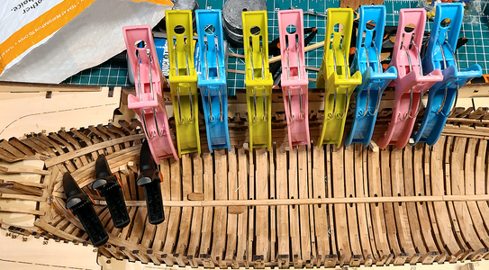
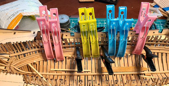
Then I bend (not much required here - 1.3mm strips moistened and bent by hand) the final bow pieces, gradually reduce the length until they fit really tightly in place, minimizing the clamping required, because clamping in this area is more difficult:
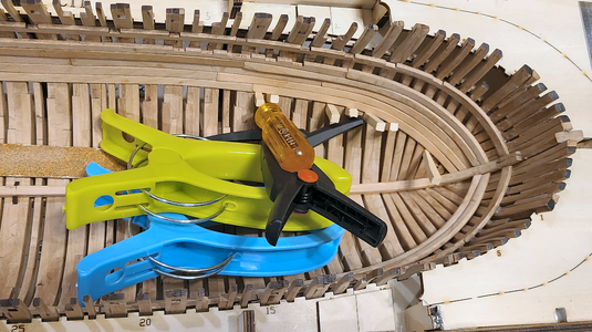
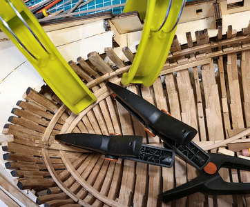
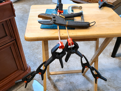
Sometimes clamps are used for rather unorthodox purposes. ;-) The main problem in installing all of this is clamping securely in place while drying. Small wedges have helped too.
Here I've added three rows of planking beneath the supports, 'D' through 'F':

Since my frames aren't perfect and vary in line some, I used a thicker glue here: Titebond Quick & Thick. Since it's so thick, it can be applied in a thick blob, and doesn't run down the frames.
No reason at this point not to just continue down towards the keel. Due to the clamping involved, and wanting to be sure everything is secure before going further, I can only do 1 strip of planks per day, so it takes a while. But I get to stare at it, think and plan in the meantime. My planning has always been better than my building anyhow.
As mentioned above, most of the pieces being put into place appear more curved than necessary as they are placed:

This is probably the least curved, but you get the idea. Near the center of the model, straight strips would be preferred to curved ones like this, since a single clamping in the center would hold the strip to the proper curve, while this way each end needs clamping.
I've been proceeding from aft toward bow in placing the pieces. The aft piece is pretty easy to place, as it fits well, and the middle piece(s) are easiest to fit as well as to clamp:


Then I bend (not much required here - 1.3mm strips moistened and bent by hand) the final bow pieces, gradually reduce the length until they fit really tightly in place, minimizing the clamping required, because clamping in this area is more difficult:

Sometimes clamps are used for rather unorthodox purposes. ;-) The main problem in installing all of this is clamping securely in place while drying. Small wedges have helped too.
Here I've added three rows of planking beneath the supports, 'D' through 'F':

Since my frames aren't perfect and vary in line some, I used a thicker glue here: Titebond Quick & Thick. Since it's so thick, it can be applied in a thick blob, and doesn't run down the frames.
No reason at this point not to just continue down towards the keel. Due to the clamping involved, and wanting to be sure everything is secure before going further, I can only do 1 strip of planks per day, so it takes a while. But I get to stare at it, think and plan in the meantime. My planning has always been better than my building anyhow.


