
-

SUBSCRIBE TO SHIPS IN SCALE TODAY!
The beloved Ships in Scale Magazine is back and charting a new course for 2026!
Discover new skills, new techniques, and new inspirations in every issue.
NOTE THAT OUR NEXT ISSUE WILL BE July/August 2026 -

Win a Free Custom Engraved Brass Coin!!!
As a way to introduce our brass coins to the community, we will raffle off a free coin during the month of August. Follow link ABOVE for instructions for entering.
You are using an out of date browser. It may not display this or other websites correctly.
You should upgrade or use an alternative browser.
You should upgrade or use an alternative browser.
CAF HMS Granado 1:48 POF
- Thread starter Adiefenbach
- Start date
- Watchers 20


Good question. Don't have a good answer at this point. Will have to deal with it either way.

Many thanks for showing us the details of the joint and your solution with the screws.
Very interesting to see ......
Very interesting to see ......
This can be only answered when we take a look at the cross section where either the frame with all parts and the location of the wales are shownIf you install them from the outside though, won’t they leave a larger hole to fill from the countersunk head? Or will they all be covered by the wales?
I have the feeling that the screw hole will be afterwards covered by the lowest timber of the wales


This can be only answered when we take a look at the cross section where either the frame with all parts and the location of the wales are shown
I have the feeling that the screw hole will be afterwards covered by the lowest timber of the wales
View attachment 272361
I think that you will need to have the hull "fully assembled " for the wale installation or if you want to add a few planks.
@Uwek how will you unscrew the screw if the wale is covering the screw head ?
I need to go and take a good look to my kit drawings to understand if what I am writing is correct or we really need to use "something" that can be pulled out from either side. Like brass wire suggested by Tom on the 3D drawings. Or Pins or nails with/without their heads.
Daniel
Last edited:
If you install them from the outside though, won’t they leave a larger hole to fill from the countersunk head? Or will they all be covered by the wales?
Are you planning to fill the holes?
I don't see them as an esthetical issue.
Daniel
When the screw heads are inside - no problem, because you can install than all wales -> you only have to shorten the screws in such a way, that the peak is not looking out of the frameI think that you will need to have the hull "fully assembled " for the whale installation or if you want to add a few planks.
@Uwek how will you unscrew the screw if the wale is covering the screw head ?
I need to go and take a good look to my kit drawings to understand if what I am writing is correct or we really need to use "something" that can be pulled out from either side. Like brass wire suggested by Tom on the 3D drawings. Or Pins or nails with/without their heads.
Daniel
when the heads are outside, I think you have to stabilize the complete structure with the inner clamps
Solution with screws, or pins or something else - they have to be removed once - and I guess this will be only possible when both of the hull parts are stabile enough -> we need really a detailed preparation work to understand the structure and the possibilities...... very interesting problem, and I guess CAF prepared it well, that it is working well

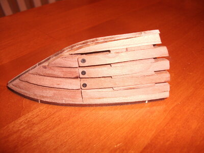
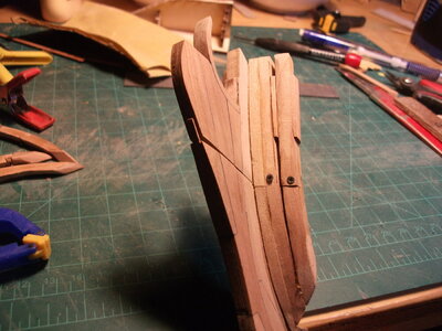
When I asked the question of how you would have removed the screws I did not take into consideration the possibility that you proposed, I thought that the screws were inserted laterally to the rib that is moved by 180 ° with respect to the insertion of your screw therefore impossible to remove for the presence of the other ribs. Thanks for enlightening meAn update on the temporarily joining the upper section of the rib to the lower section. I have tried out my small screw plan and the results are very promising so far. This is my first attempt, rib 31, a large center rib made up of three individual ribs. This is the bottom section
View attachment 272329
This is the upper section that I am trying to fit temporarily but firmly
View attachment 272311
This is how they dry fit
View attachment 272314View attachment 272321
Once dry fit, I clamped and drilled a small hole to engage both sections
View attachment 272322
Then screwed the sections together
View attachment 272324View attachment 272326
Although difficult to see, the small phillips head screw is in place, with the head on the inboard side of the rib. Could go the other way I suppose but as I think the tendency will be for the upper section to want to fold inwards, I thought that having the head of the screw inboard gave it most strength. Knucklehead engineering on my part I suppose. Anyway, as the screw is 10mm long, it does protrude through the other side but can be cut off with a good set of nippers. Once the screw is installed, this joint is very secure and I am happy with the result. I will complete this rib and work on the rest of the large 3x ribs before attempting to do this on the narrower 2x ribs. I think they will be more challenging but am hopeful that the result will be successful.
Have been plugging along on this kit, putting together the more than 50 ribs that are required. Lots of time on the spindle sander trying to get the various contours right. There are some pretty amazing shapes that you have to achieve. I agree with an earlier post by pianoforte that working with wood is extremely enjoyable so overall it has been a lot of fun.

Have gotten the keel assembled and installed in the jig. Based on other posts, I tried the graphite powder mixed with the wood glue for the joints and I really liked the outcome. One issue though is when sanding it down, the graphite dust generated from the sanding wants to slightly darken the surrounding wood and you have to be careful.


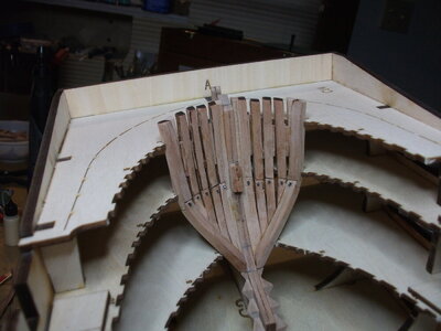
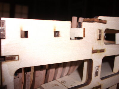
This is my first plank on frame whole ship experience (had a great time building the Bonne Homme Richard cross section earlier) and the bow structure was a challenge for me. The kit provides an interesting set of port and starboard side mini-jigs to get the timbers shaped up but there is a lot of tricky spindle sanding to do here and I found that my pieces that seemed to fit ok in the jig had to be adjusted substantially to actually fit in the bow. You can see from these photos that I have continued using small screws to hold the upper to lower sections of the frames together in anticipation of splitting the upper and lower hull sections. I am driving the screws in with the heads on the outside of the hull as it looks to me like the interior of the hull gets very built up before we get the hull out of the jig and ready to split. More on that in a minute.


The above shots show one of the mini-jigs and how things sort of fit together in it before moving to the bow itself. Next is how things started to look once I moved to the bow.

This is how it looks in the jig so far.


This part has been very challenging for me. It feels like you are working in 3 (or maybe 4) dimensions, getting the various curves and flats to line up properly. I am sure there will be some remedial work required once this gets out of the jig and I can clearly see the outside results.
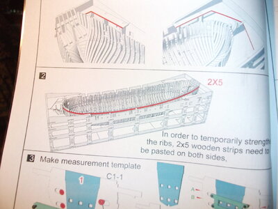
Regarding my use of screws, so far, and it is early, I do recommend it. They hold the two sections of a frame together firmly and are much more solid than just wire. With as much manipulation as I have had to do the get things to fit properly in the bow, the screws have been a life saver for me. Looking at the first page of Part II of the kit, we start out on step 2 putting a "wale" of 2 x 5 mm wood around the upper sections of the the frames, shown in red on the diagram. This is to provide some structural stability. Nowhere in the instructions or plans is a precise elevation given for this "wale" but I will approximate from the drawings in the booklet. I think it would be very difficult to get this wale mounted correctly without the upper sections of the ribs being firmly in place, thus the screws. Would love to know if anyone has any better ideas because I am game.

Have had fun with this kit so far, it is challenging but the quality of materials is outstanding and good to work on. I have had several occasions to contact Tom at CAF and every time he has responded quickly and helpfully, providing anything that I have needed. The customer service is just fantastic and is a real credit to Tom and his organization. More to follow.
Have gotten the keel assembled and installed in the jig. Based on other posts, I tried the graphite powder mixed with the wood glue for the joints and I really liked the outcome. One issue though is when sanding it down, the graphite dust generated from the sanding wants to slightly darken the surrounding wood and you have to be careful.
This is my first plank on frame whole ship experience (had a great time building the Bonne Homme Richard cross section earlier) and the bow structure was a challenge for me. The kit provides an interesting set of port and starboard side mini-jigs to get the timbers shaped up but there is a lot of tricky spindle sanding to do here and I found that my pieces that seemed to fit ok in the jig had to be adjusted substantially to actually fit in the bow. You can see from these photos that I have continued using small screws to hold the upper to lower sections of the frames together in anticipation of splitting the upper and lower hull sections. I am driving the screws in with the heads on the outside of the hull as it looks to me like the interior of the hull gets very built up before we get the hull out of the jig and ready to split. More on that in a minute.
The above shots show one of the mini-jigs and how things sort of fit together in it before moving to the bow itself. Next is how things started to look once I moved to the bow.
This is how it looks in the jig so far.
This part has been very challenging for me. It feels like you are working in 3 (or maybe 4) dimensions, getting the various curves and flats to line up properly. I am sure there will be some remedial work required once this gets out of the jig and I can clearly see the outside results.
Regarding my use of screws, so far, and it is early, I do recommend it. They hold the two sections of a frame together firmly and are much more solid than just wire. With as much manipulation as I have had to do the get things to fit properly in the bow, the screws have been a life saver for me. Looking at the first page of Part II of the kit, we start out on step 2 putting a "wale" of 2 x 5 mm wood around the upper sections of the the frames, shown in red on the diagram. This is to provide some structural stability. Nowhere in the instructions or plans is a precise elevation given for this "wale" but I will approximate from the drawings in the booklet. I think it would be very difficult to get this wale mounted correctly without the upper sections of the ribs being firmly in place, thus the screws. Would love to know if anyone has any better ideas because I am game.
Have had fun with this kit so far, it is challenging but the quality of materials is outstanding and good to work on. I have had several occasions to contact Tom at CAF and every time he has responded quickly and helpfully, providing anything that I have needed. The customer service is just fantastic and is a real credit to Tom and his organization. More to follow.
Attachments
-
 DSCF1059.JPG248.3 KB · Views: 25
 -
 DSCF1054.JPG140.8 KB · Views: 21
 -
 DSCF1061.JPG213.2 KB · Views: 18
 -
 DSCF1044.JPG254.5 KB · Views: 17
 -
 DSCF1045.JPG187.9 KB · Views: 15
 -
 DSCF1048.JPG199 KB · Views: 16
 -
 DSCF1049.JPG177.1 KB · Views: 13
 -
 DSCF1050.JPG171.2 KB · Views: 13
 -
 DSCF1051.JPG242.3 KB · Views: 12
 -
 DSCF1052.JPG196.8 KB · Views: 12
 -
 DSCF1054.JPG140.8 KB · Views: 15
 -
 DSCF1055.JPG162.5 KB · Views: 19
 -
 DSCF1059.JPG248.3 KB · Views: 20
That “wale” looks to me to be a temporary batten to strengthen the upper frames at this point, I would think it will be removed later as it is placed way too high to be part of the wales which would start below the gunport sills by at least a plank width, I think it is also too thick to be planking, not sure but would think the planking will be 1-1.5mm thick, and lastly, it runs the full length of the hull with no joints and there isn’t a plank on the ship that does that…. So it probably gets removed with alcohol (if using pva or similar glue) or CA debonder…. Nice work so far, your frames are well executed and look awesome…. I’ll be starting on mine pretty soon, got 6” of snow today….
Thanks very much. That upper "wale" is still in place at the end of part II. Don't know what part III instructions will reveal. The instructions in step 2 refer to it being "temporary", I sure as heck hope I won't have to remove it. Enjoy the snow, am jealous
I think also, that the 2*5mm are only temporary strengthening strips, like written in the manual and not the final permanent wales.
Check the manual when the outer planking is described .... upps - section 3 or?
Check the manual when the outer planking is described .... upps - section 3 or?
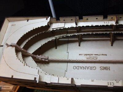
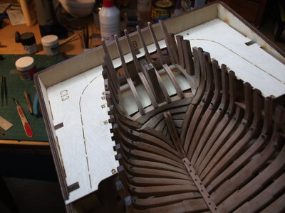
Hope all have had a wonderful holiday season so far. Have been doing a lot of sanding and fiddling on this kit over the holidays and have completed the construction and installation of all the ribs for the hull. Have provided a couple of photos to show progress. My use of screws to temporarily connect the upper and lower sections of the hull seems to be working ok so far. Time will tell. I had a few issues, particularly with the sternmost ribs, where I didn't pay enough attention to the alignment of the rib parts with the plans for each rib. I thought I had but when I encountered a fit problem during installation, more often than not my rib did not precisely match the plan. Lesson learned-pay very close attention to each rib plan.
The overall look:

Bow and stern:


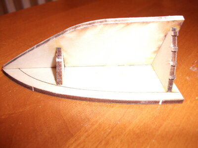
As shown in post #29, when you start part II, the first thing you do is cut away the upper deck of the framing jig at the bow and stern, in preparation for installing the "temporary" strengthening strip. This is what you get:

I then had the idea to use the bow part of the framing jig that is removed during the construction of the jig for shaping the strengthening strip. Soaked the 2x5 strips provided in the kit for about 20 min in hot water and then clamped them to the discarded jig part with the below result. 2x5 is pretty stout so soaking more than less is a good idea:

I then took some time off from wood work to build the oven which is provided as a separate kit in the box. This was a lot of fun to build and play with and the kit is very well created by CAF. I am not going to attach the chimney section to the oven part until installation in case I encounter some alignment issues. Playing it safe. Here is how my oven turned out:


Have painted all the brass sections flat black and will continue to work the shading on the oven. It was a fun little project and a nice break from woodwork.
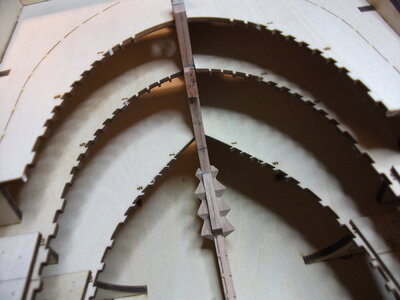
Then, prior to installing the strengthening strip (have to screw up the courage to do that), started the next step of construction of a series of 4 ingenious templates that CAF provides. The pieces provided go together very well and I am anxious to see how they work during the next phase of construction:


Next step for me is installing the strengthening strips that I have already formed. Am still scratching my head regarding best way to attach just in case it does have to be removed later, which I think is likely. May just use small amount of water soluble glue, just enough to hold.

Happy to consider any ideas that you all might have.
So far, this has been a very enjoyable kit to build, most of the head scratching/remedial sanding has been the result of my own mistakes but the quality of materials provided makes it possible to make adjustments fairly easily. I did find the stern framing to be quite challenging, aft of about frame 45, as this is my first real plank on frame full hull kit.
Happy New Year to all.
The overall look:
Bow and stern:
As shown in post #29, when you start part II, the first thing you do is cut away the upper deck of the framing jig at the bow and stern, in preparation for installing the "temporary" strengthening strip. This is what you get:
I then had the idea to use the bow part of the framing jig that is removed during the construction of the jig for shaping the strengthening strip. Soaked the 2x5 strips provided in the kit for about 20 min in hot water and then clamped them to the discarded jig part with the below result. 2x5 is pretty stout so soaking more than less is a good idea:
I then took some time off from wood work to build the oven which is provided as a separate kit in the box. This was a lot of fun to build and play with and the kit is very well created by CAF. I am not going to attach the chimney section to the oven part until installation in case I encounter some alignment issues. Playing it safe. Here is how my oven turned out:
Have painted all the brass sections flat black and will continue to work the shading on the oven. It was a fun little project and a nice break from woodwork.
Then, prior to installing the strengthening strip (have to screw up the courage to do that), started the next step of construction of a series of 4 ingenious templates that CAF provides. The pieces provided go together very well and I am anxious to see how they work during the next phase of construction:
Next step for me is installing the strengthening strips that I have already formed. Am still scratching my head regarding best way to attach just in case it does have to be removed later, which I think is likely. May just use small amount of water soluble glue, just enough to hold.
Happy to consider any ideas that you all might have.
So far, this has been a very enjoyable kit to build, most of the head scratching/remedial sanding has been the result of my own mistakes but the quality of materials provided makes it possible to make adjustments fairly easily. I did find the stern framing to be quite challenging, aft of about frame 45, as this is my first real plank on frame full hull kit.
Happy New Year to all.
Attachments

Excellent progress.
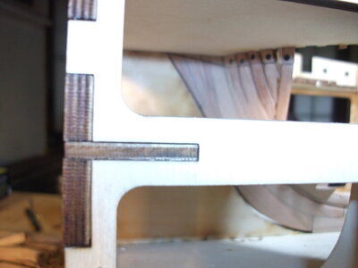
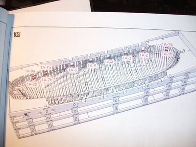
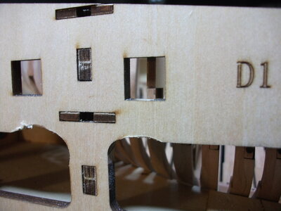
After my last post, got to work installing the templates that I just finished making and discovered a problem with the fit that may be an issue with the build instructions. Maybe Tom can weigh in and clarify. This is not a big issue and I think I can easily work around but wanted to alert other builders of the issue. When installing the frames into the jig, the instructions clearly call for you to measure the height of the gun port frames against cut outs provided in the jig (there are 4 on each side of the hull). This direction is provided in step 32 of the manual. A nice straight 4x4 piece of wood is provided to do this. Although my photo isn't the clearest, the drawing shows that the 4x4 should be resting on top of the gun port rib and flush in the cutout of the jig

When you get to step 34, the lower crossbeams for the gunports (sorry I don't know the correct term) are installed (shown in red):

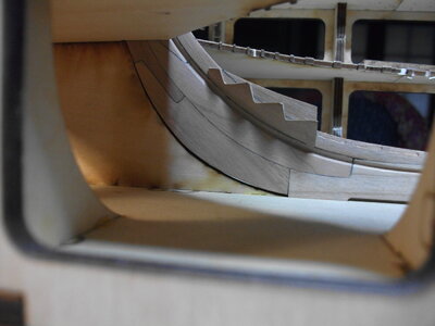
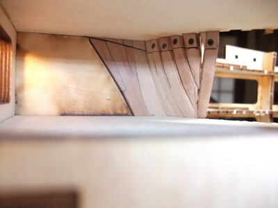
Fast forward to installing the templates described in my last post. They do fit very well with one issue. The instructions clearly show the cross member of the template fitting snugly against the front face of the notch in the jig, and resting on the bottom of that notch:

However, since the gunport lower crossbeam was installed after setting the height of the gunport rib flush with this same notch in the jig, the template now rides on this gunport crossbeam, raising the template the 2mm or so thickness of the gunport lower crossbeam. This is how they fit together now (pictures are taken from astern, the templates are flush with the front of the notches as required):


I don't think that this is a huge deal, but I do think I have to modify the template arms slightly so that the template lowers the additional 2mm or so into the hull. This is because the templates are used to set the height of stiffening planks that run above and below the split hull joints. I think, and this is where Tom or a smarter builder than I might weigh in, that the elevation of these stiffeners (first things to go into the hull) will have an impact on the fit of many other of the internal components. Thus the warning in the instructions to "pay attention to the position of the templates". I intend to notch the template arms where they rest on the gunport lower crossbeam such that the template arm rides properly on the cutout of the jig and the whole template settles a little more into the hull..
Cheers!
When you get to step 34, the lower crossbeams for the gunports (sorry I don't know the correct term) are installed (shown in red):
Fast forward to installing the templates described in my last post. They do fit very well with one issue. The instructions clearly show the cross member of the template fitting snugly against the front face of the notch in the jig, and resting on the bottom of that notch:
However, since the gunport lower crossbeam was installed after setting the height of the gunport rib flush with this same notch in the jig, the template now rides on this gunport crossbeam, raising the template the 2mm or so thickness of the gunport lower crossbeam. This is how they fit together now (pictures are taken from astern, the templates are flush with the front of the notches as required):
I don't think that this is a huge deal, but I do think I have to modify the template arms slightly so that the template lowers the additional 2mm or so into the hull. This is because the templates are used to set the height of stiffening planks that run above and below the split hull joints. I think, and this is where Tom or a smarter builder than I might weigh in, that the elevation of these stiffeners (first things to go into the hull) will have an impact on the fit of many other of the internal components. Thus the warning in the instructions to "pay attention to the position of the templates". I intend to notch the template arms where they rest on the gunport lower crossbeam such that the template arm rides properly on the cutout of the jig and the whole template settles a little more into the hull..
Cheers!
Attachments
Looks great . It's a interesting building process to follow. Really like it to follow
Adi- do the templates need to be lowered to to set the stiffening planks or are they sitting in the correct position now? It looks to me on the side view plans that your gunport sills are in the correct position, the sweep ports bottom edge are in line with the lower gun port sills top edge so maybe the plans depicting the template crossbars position is wrong? Depends on how the template lines up currently I guess, it they need to be lower then you need to notch but if not then you are good to go?
Thanks for all the comments. Having gone over all the drawings provided and photos on the CAF website, I do think that the elevation is critical and I adjusted the template arms (cut in small notches) to ride a little lower on the gunport sills. Fingers crossed as I move forward.
You are inspiring me to get back into my Granado build. ")