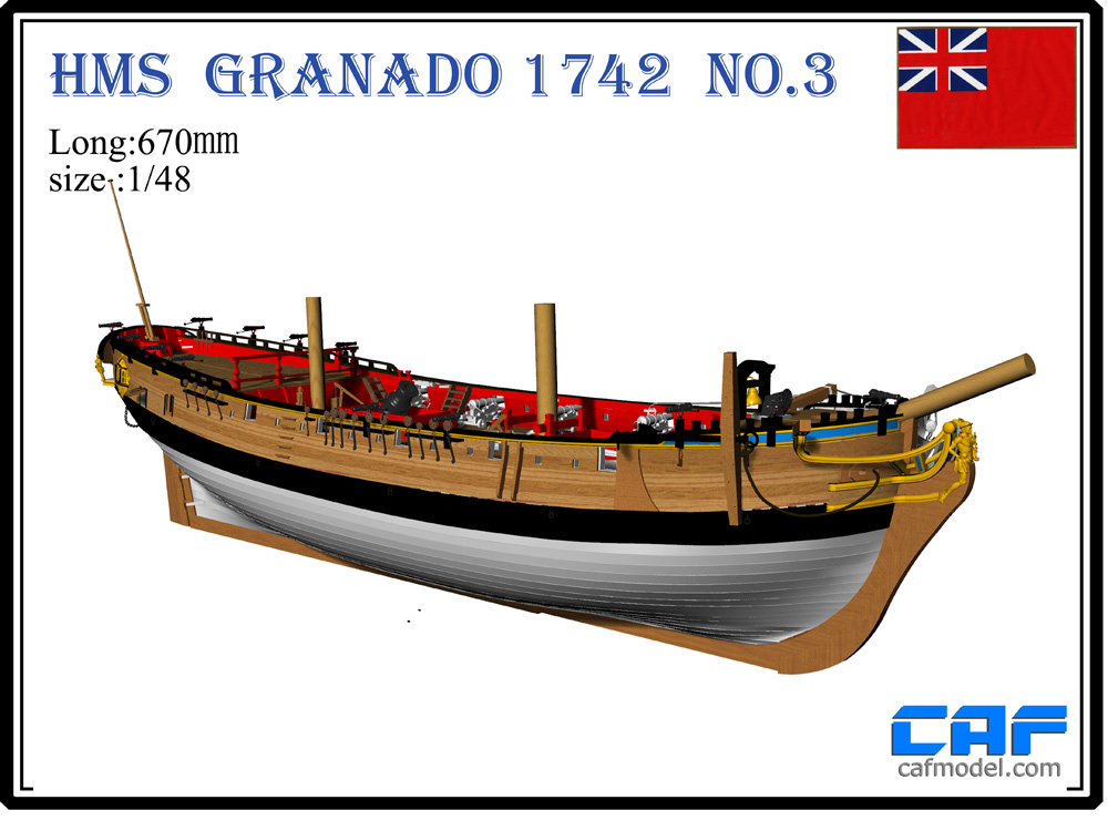
CAF HMS Granado 1:48 POF

It is fantastic for myself, and probably others, that you explain a few issues you have here and there. But !!!!! Nevertheless !!! To my eyes looks fantastic !!!!!!!!.

I hope I can achieve your level when I built mine. It will be probably in 1.5 years. Let's see.

Best
Daniel
 
Very good work - looking very good
The kit content a lot of details and you are making a very good job producing a very good model :cool:

Step by step I am finishing my section model, so I guess in some weeks I am able to start my full hull Granado
 
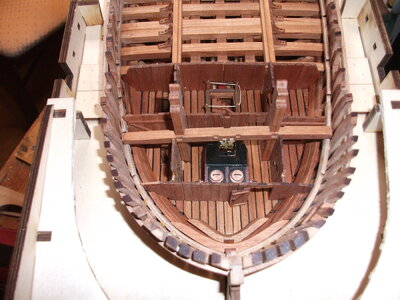
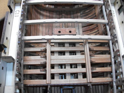
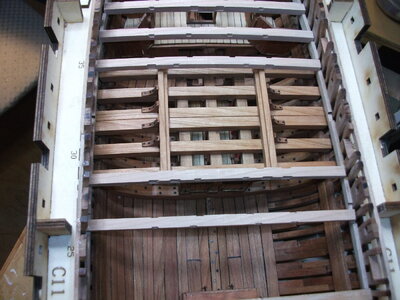
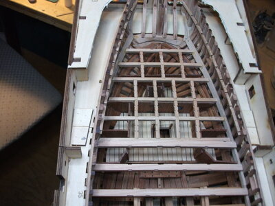
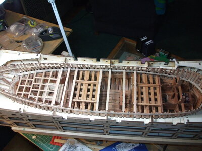
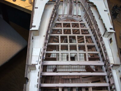
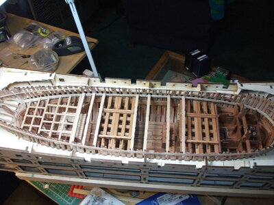
Have pretty much completed Part 2 of this kit. Made it to the back of the directions :) The photos show how she looks at this point, the only parts missing are the masts and the three forward athwartships beams. Keeping the masts out for now, until I can see how this whole shebang comes together. Also have only dry fit the major athwarthships beams for the same reason (those beams are the ones that have not been oiled). The directions explicitly call for not gluing some of those beams but I remain cautious on the rest. The lattice work aft was quite challenging and I think my final product, while pretty well aligned, is probably a bit higher in the ship than planned. Having completed all the steps in the kit and having made all that is called for to be made, there is plenty of strip wood left over, Tom/CAF were very generous in what is provided. I remember counting the various strips/sizes to make sure I got everything in the parts list. Based on what is left over, not an issue by any means. There is one, and only one, head scratcher that I encountered in the final steps. The forward most athwartship beam, that gets mounted just aft of the forward bulkhead where the stove is, is about 3/8 of an inch too short right out of the CNC machined sheet. I can't sort out why. That measurement comes right off the jig and the fore/aft location is clearly set by the pre cut notches in the inner "wale" but, for some reason, as provided, it can't possibly fit. I have glued some scrap cherry on to each end and will sand down to fit. All other beams are great. Anyway, will take some of the spare scrap wood and make some small lockers/racks/cabinets to install throughout the ship while waiting for Part 3 to come on line. Also plan to make a few of the smaller barrels/casks that came with the BonHomme Richard kit and position them in the ship. Not sure how much of that kind of outfitting will come in Part 3. Will have to likely head to the stash to pull another kit while I am waiting for Part 3. Patience is a virtue I think.
This is where I am so far:
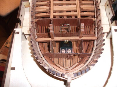
DSCF1168.JPG
Bow shot. The windlass beam assembly just aft of the stove is not glued at this point, just dry fit, per the directions.
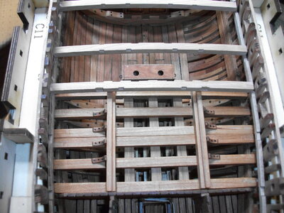
DSCF1169.JPG
Moving aft, the above shot shows the forward ammo storage and beams. The three unfinished beams at the top half of the photo are not yet glued in.

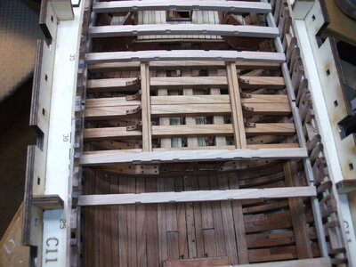
DSCF1170.JPG
Moving further aft, the aft ammo storage locker with some unfinished athwartships beams.

DSCF1171.JPG
The stern, showing the deck support structure. This was quite challenging to get level port to starboard and fore/aft. I believe that this structure comes away with the upper portion of the hull.

This is the whole enchilada, minus masts and the forward beams.
DSCF1172.JPG

Am very curious about a couple of things. 1. When will part 3 be released? It will happen when it happens but I would be lying if I said I am not anxious to keep going. 2. When do we actually separate the hull sections (upper/lower). I can't see doing that without pretty much destroying the jig but this is my first full POF and I am curious.

Will be avidly watching Bryian's build log to see "What I should have done"

Cheers.

DSCF1168.JPG

DSCF1169.JPG

DSCF1170.JPG

DSCF1171.JPG

DSCF1172.JPG
 
As mentioned earlier - you are very fast builder - and - it is looking very good
On the web-page it is still mentioned, that package 3 will be available in March, and as I know from Tom, he is hardly working on the preparation.
So I am pretty sure, that you have to wait only some more weeks to get the next session.......

 
Hope all had a Happy Thanksgiving and survived the holiday. Have been working on Part One of this CAF Granado kit for a while now. Part Two is waiting in the wings. Have completed all of the main ribs and have been impressed by the quality of the rib design and of the jig for assembly.
View attachment 271674
Everything is dry fit at this point as I get ready to tackle the trickier bow and stern rib structures. While checking the fit of the keelson pieces with the installed ribs, I noticed that ribs 8 through 15 sat too high on the keel and were impacting the fit of the forward keelson piece. During initial construction, these ribs require substantial sanding for contour and I was pretty careful to follow the lasered lines provided on each piece to get the contours right. Even so, I had this problem with ribs 8 through 15. Not sure if anyone else has seen this yet. My solution was to carve out a small channel in the inside bottom curve of the rib to accommodate the keelson. Rib 8 had the deepest cut and 15 had the shallowest. Below is rib 8 followed by rib 15
View attachment 271677
Below is rib 15View attachment 271676
By making these mods, the forward keelson piece fits snugly against the top of the keel section at the bow. Not sure if I have bought myself problems down the road but this seems to be working for now. Ribs aft of nr 15 all ride nicely on the keel and the dry fit of the keelson is working well. Rib 9 and rib 44 are loose in the jig (have side to side play of about 5mm). When I checked against the plans, my rib 9 was spot on with the drawings, rib 44 looks to be my bust as it is slightly narrower than the drawing. Will sort that later.

Regarding the split hull issue on this kit, the instructions call for the use of pieces of wire to temporarily hold the upper pieces of the various rib sections in place with the lower sections while assembling the upper section. I have done some dry runs using scrap wood and have not had much luck. What has some promise is the use of railroad track screws which are about the perfect size.
View attachment 271680View attachment 271678
I was able to get these on Amazon but they are carried in a variety of hobby/train shops. As shown on the box, they are 10mm in length and 1.4mm diameter. Phillips head. What I am hoping is that with these mini screws, I am going to get more "bite" in holding the small pieces together temporarily than I would with smooth pieces of wire. In any case, once these screws are removed, will have small holes to fill/dress (would have that issue with wire as well). I am going to try to muster the courage in the next few days to start drilling some holes in the ribs and putting this theory to the test. Would appreciate any comments/thoughts/better way if anyone has opinions to share.

View attachment 271675
Hallo @Adiefenbach
we wish you all the BEST and a HAPPY BIRTHDAY
Birthday-Cake
 
Thanks very much. While waiting for part 3 of Granado to come online, started Model Expo's Confederacy. Great kit and fun to build. May order the Granado part 3 as a belated birthday present Thumbs-Up
Hi

I was reading your postings about the Victory and started to wonder what happened with the Granado. Have you started part 3 ?

All the best !!
Daniel
 
Back
Top