Daniel, appreciate your interest and the questions. Makes me think more about what I am doing. In answer to your questions, the screws have worked very well for me. Better than smooth wire in my opinion because they actually hold things together. Lots of frames to manage. The wider frames are easier to deal with because they have a natural engagement top to bottom while the narrow frames are very touchy.
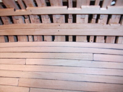
View attachment 280761
In the photo above, the left circle shows the easy to work wide frame while the right hand circle shows the thin one. You could probably get away with using wire on the wide ones, I could not have managed with just wire on the thin ones.
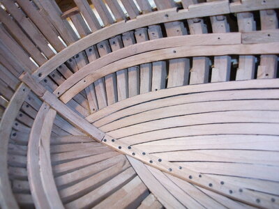
The "temporary" reinforcing strip is installed on the outside of the upper half of the hull. Have the three permanent planks installed on the interior of the hull, one above the "cut line" and two below. The hull is very sturdy at this point. I have removed 90% of the screws, the ones at the bow are still in place, screwed in from the outside, because they are tough to get at at this point. Will likely wait till the hull is out of the jig to get at those. The photo below shows the bow in the jig.
View attachment 280759
I also learned a lesson which might be useful. Being somewhat obsessive/compulsive, I screwed in virtually all the screws all the way in, seating the head in the wood slightly. In hindsight, in most cases this was a mistake. It enlarges the size of the hole where the head is, risks splitting the frame, and only occasionally provides usefully more grip. Was necessary in a few frames but overall not so much. Just having the threaded shaft of the screw holding both pieces of frame together was sufficient in most places to make the frames manageable. Sometimes had to screw them tight to get sufficient hold. Hope that makes sense.
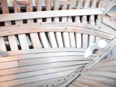
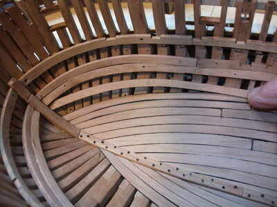
View attachment 280766View attachment 280758
The above photo on the left shows a split thin frame upper end (right side of the photo). The photo on the right shows how the head of the screw enlarges the surface area of the hole. Not seating the head of the screw into the wood should eliminate this.
Cheers,
Andy


")