CAF Granado 1/48 PoF Bomb Vessel by Signet

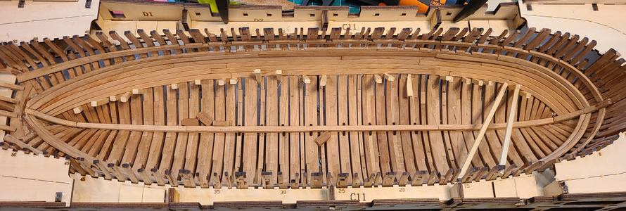
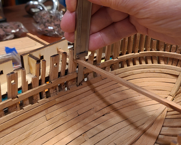
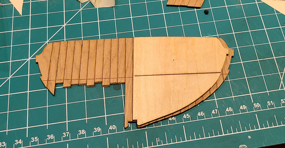
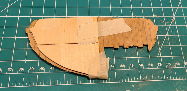
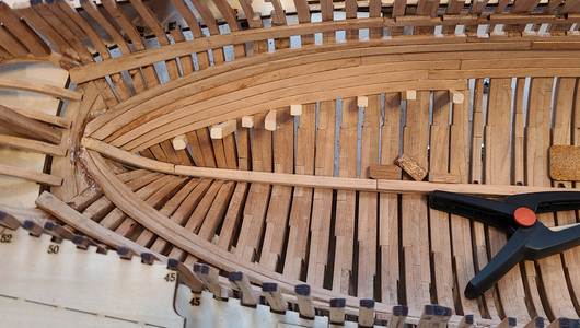
Continuing on with the Port inner planking, it's difficult to get clamps or weights to hold the planks while glue is drying, so wedges work fairly well:
1718156103580.png
1718156126421.png
The above is the last plank that went in easily, without bending a lot. Also, the first several planks (going downwards) were longer than required, so were trimmed (as they should be and as noted in the instructions - I'm not complaining).

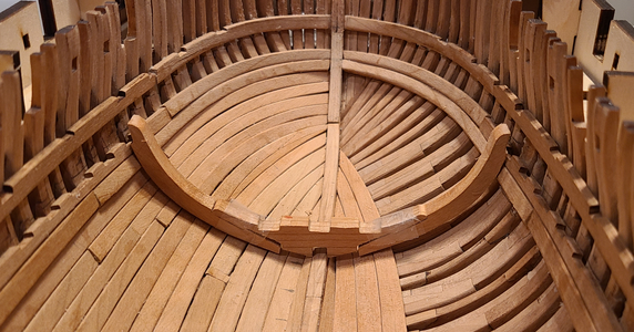
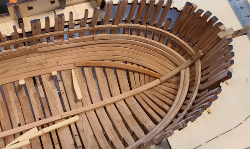
Bow planks, especially, did not have sufficient curve at this point, requiring a lot of bending and clamping to position:
1718156255521.png
By leaving the bow planks until last, they could be trimmed just a bit at a time until they force fit into the space left, minimizing clamping.

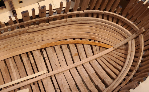
There was no way to force this next bow plank to fit, so I decided to leave a gap, hoping the rest would fit better, and fill the gap later:
1718156354453.png

NOTE: I will note again that I am doing this planking backwards (okay, upside-down), compared to the instructions, which state you should start at the bottom and work up. I have no doubt that the gaps and such would have worked better that way, but I was not confident on the final/top plank fitting in place against the heavier riders that support deck and other supports. I felt it was most important that they fit properly at the top, which I think will be most visible and critical, and have accepted the problems I am experiencing as the price I have to pay to do that.

In general, it seems to me, doing the planking in the order that I am, that lower bow planks are not curved enough, while center planks are bent curved too much.
1718156627594.png
You will also note that while the first few plank combinations were longer than required, from about 'G' plank down they are too short. Again, I accepted this and planned to fill the gaps later, as well as cover poor looking areas with barrels and such.

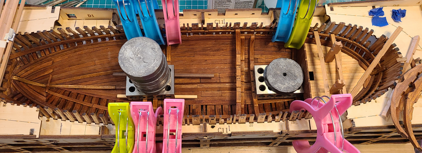
The clamps I have don't help much here, but the weights are starting to be used with good effect while glue dries:
1718156760451.png

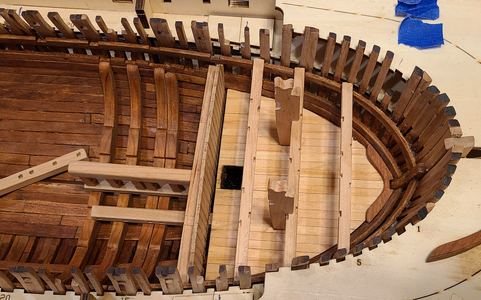
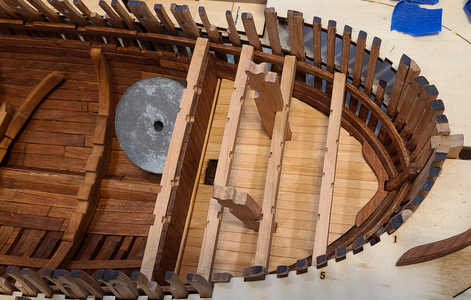
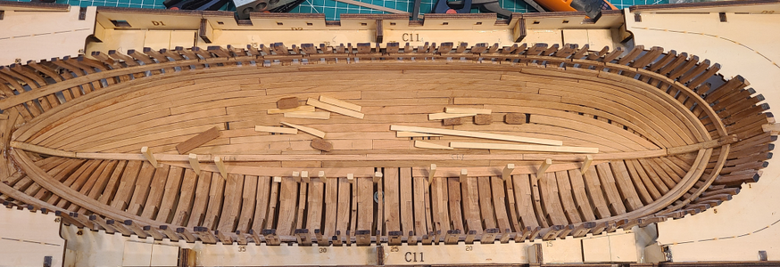
Here I've completed the port planking, and am starting the starboard planking, extending it to match the port side:
1718156812176.png
I only intend to include some of the port planking, leaving most of it off to hopefully provide a view of inside detail below the waterline.

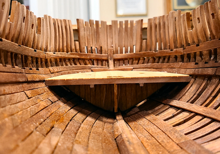
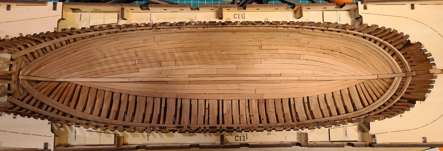
Here I've completed all the planking I'm doing at this time:
1718156897913.png
I have filled most of the end-to-end gaps left by doing the planking top-down rather than bottom-up, as I said above. There are still gaps which I may fill later, or may caulk or leave alone, depending on their visibility and appearance. I'm not going to spend a lot of time fixing things that will not be visible, and will not be doing treenails, at least on these planks. I tried a few nails, and don't feel capable of it, but again, any treenails or other fastener details would be limited to highly visible areas.

I know the craftsmanship, no, the lack of decent craftsmanship, shows clearly in the above photo. I'm not under any delusions that it looks good. Every other builder of this kit will abhor such sloppy work, with good reason. But this is my first, and probably my last, plank-on-frame kit, and I honestly think that when complete, it will look good. At least I'll be happy with it, I hope, and those viewing the model will be impressed that the above consists of nearly 1,000 separate pieces.

I think I will try to work on some of the cross-supports for the mortars next. I may well add additional starboard inside planking, but I will leave inside details loose for quite a while, to help determine visibility of details and what, if any, additional planking to add.
 
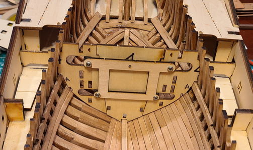
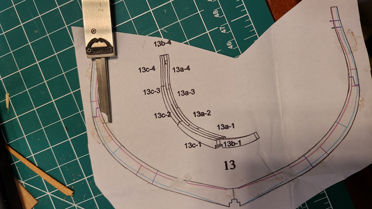
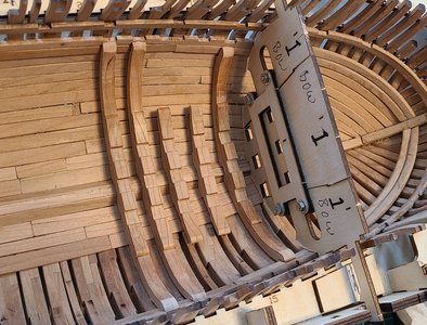
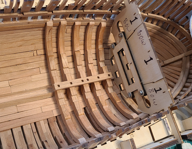
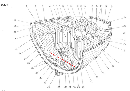
I'll be using the four templates supplied with the kit to locate all of the internal structure and details. These fit quite well in determining the top 2mm thick support 'A' located in the inside of the hull, somewhat less so with 'B' as mentioned previously, so while these templates fit well before, they don't fit as well now. I know a portion of them is to be removed after 'C' is installed, so they can fit better, but I think I can remove much more of the sides of them and not defeat their purpose: while the outer sides can and will be trimmed, the holes for locating mortar and other structures will not be changed, and the 2 gunports in combination with the keel properly locate these items. Starting with template 4, I reduced the side widths to fit better:
1718157659060.png
On the left is the original shape, with the extra portions on the template removed and just a bit of sanding. On the right is my much-more-modified version, to clear all inside planking and such. Why was this required? Probably because my frames aren't all at exactly the right profile, and planks sit on the highest of them, and also planks don't fit as tightly against the frames, especially where they are twisted. This will probably affect the inner structures, but I hope to adapt to them as I get to them.

Here you see the fit of this template in its location in the partially-planked hull:
1718157828827.png

As I mentioned previously, I'm leaving the sills of the gunports off until later, when I will shim or sand them to obtain an accurate height. But that won't be until the inner structure is completed, as the sills interfere with the templates riding at the correct height.
 
On to the lower supports for the mortars. I, unfortunately, chose the support furthest forward to work on first. The reason for unfortunately will be told later. After doing minimal cleanup on the three pieces, I loosely positioned them in their location in the hull structure:
1718639094528.png
Two things are noticeable here: 1) I may have "cleaned up" the joint area a bit much, because the joint doesn't fit tightly, but can rock a bit. This rocking makes the width of the support at the top change by maybe 1/8", so I was concerned about that. Secondly, it's obvious that the height of the support is too high. It must end below the notices in support 'B' and it is over 1/4" higher than that. So, what's wrong? My hull shape? The location of support 'B'? The shape of the mortar support?

I first confirmed the distance on the plans from the 4mm square sweep holes used as a reference to the bottom of the notch, and confirmed it to be correct per the plan:
1718639429526.png
then drew those dimensions on the nearest frame drawing to use as a reference:
1718639479223.png

Laying the mortar support beam and the cross beam above it more-or-less in place, it's obvious there isn't enough room for this support beam:
1718639553597.png
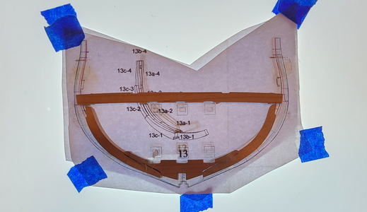
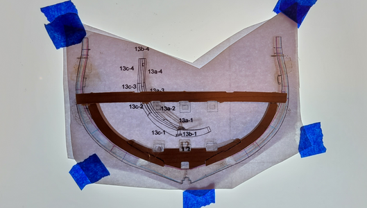
Here I've placed two neighboring frame outlines on a light tracing pad to confirm changes frame-to-frame.

Moving the mortar frame close in position, while placing the top beam in place, shows how much must be removed from the mortar frame height:
1718639619966.png
So, IMHO, this particular support frame was very inaccurate in shape, in particular in its height and notch locations.

I ended up removing over 1/4" of the top of this support frame #5 to get it to fit. My thinking, and concern, was that this would be required for all of the frames, due either to a construction error on my part, or errors in the kit parts. The next frame I made was #1, the furthest aft at this point, and surprisingly, it fit quite accurately with very little modification. Here are both in place:
1718639917823.png
So, it appeared that it was mostly this one frame that fit wrong. For whatever reason that is.

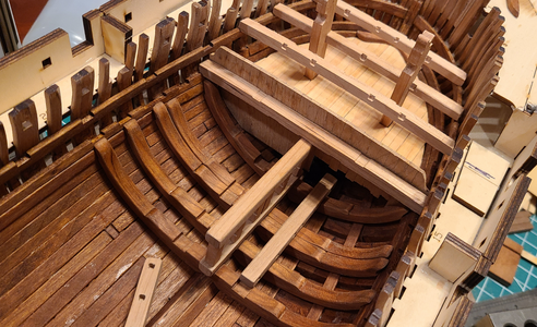
I used the first two templates #1 and #2 and a strip of wood to determine that these two supports were at the proper height for the mortar magazine structure to fit atop it. As I progressed down the series of 5 mortar support frames, I found it best to first confirm that the height of the center pieces were correct. In that way, regardless of the shape and fit of the side pieces, the magazine structure should fit properly atop the frames.
1718640312296.png
All unfinished frames now fit into place and the bottom longitudinal portion of the magazine support is fitted temporarily:
1718640425269.png
This longitudinal support did not quite fit into the notches, so initially tried filing the notches to a slightly wider opening, and squaring up the corners left by the milling. This was difficult to do free-hand, and the height and squareness of the notches tended to deteriorate. I ended up slightly sanding the sides of the beam, instead, which I could do accurately with a few thousandths, and rounding the bottom of the beam a bit. I feel this worked much better and more accurately and will continue with that method. Here are all five of these lower frames with one of the cross beams above it:
1718640866396.png
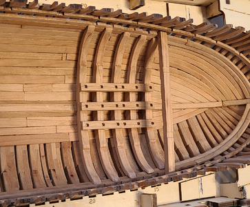
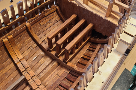
Some of these frames "snap" into place and stay really well, while others, like #5 to the right, will take clamping to confirm its position when glued in place. I will not be permanently gluing any of these items for quite some time; I want to be sure how everything fits, and then will go back to see if an occasional plank should be added to the open framing side.

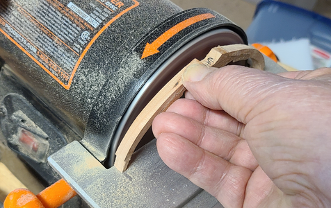
I found during final finish sanding of these frames that holding them up to a circular sander was a quick and accurate way to insure a good side finish, removing any difference in the positioning of the pieces during gluing:
1718641097133.png
Not only does this sand the area smooth, but it's sanding pretty much with the grain in all areas, and worked very well.

I'll continue on with the aft mortar frames in the same way.
 
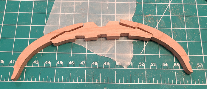
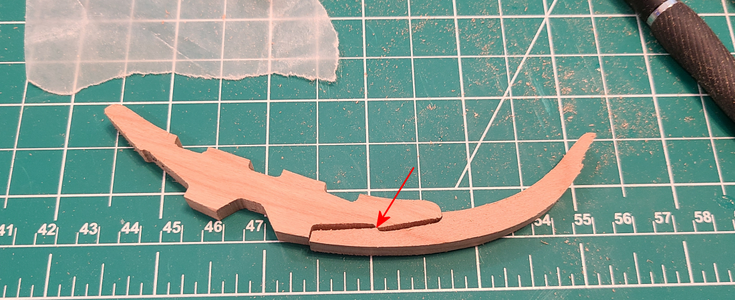
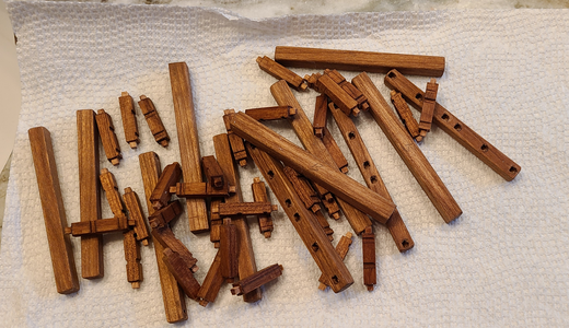
Continuing on with the supports for the aft mortar, most of these supports are cut and fit like this, before modification:
1718816466991.png
I have found it best to do as little cleanup or modification as possible, and for a good fit, this usually involves only filing both pieces slightly at this point to eliminate the interference:
1718816536503.png
The supports then fit the hull quite well, with almost no modification, usually just at the top for me.

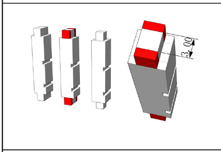
The vertical supports parts 5A-1 and 5A-2 require narrowing of the notch as shown on the plans:
1718816759943.png
In addition, the notches for the bomb supports are milled round and shallow, not square like shown above. I'm not good at modifying things by hand with files and such and having them come out square, so first made a setup to cut the 3mm extension using a small table saw. While I was at it, I checked the dimension the other direction for this "peg". I found this dimension to be too large to fit into the holes provided, and rather than trying to enlarge and square off the holes, it was easier to modify the "peg". Then I can round the peg a bit for a good fit.

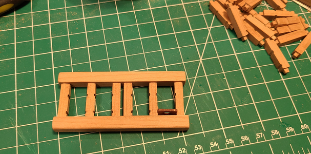
Likewise, the notches provided for the bomb shelves were not wide enough to fit the shelves. Again, making these notches deeper, more square and consistent was beyond my abilities, so I made a small jig using some scrap:

The top is grooved to fit the support, with a thin strip to locate the edge. The bottom is shown after cutting, with both grooves sawed:
1718817281593.png
Of course, I use the support slots as locations for the setting up the the correct offset to locate the new sawed slots. The completed jig with a support in place is shown here prior to use, and to the right, during use:
1718817481635.png
This process enabled me to make nice consistent slots for the bomb shelves and good fit to the upper and lower longitudinal supports:
1718817557751.png
That's it for now. But I've got to be thinking at what point I should put a finish on the wood which will shortly be covered by other structures, and at what point to make any cutouts in the frames to show details from the side. I've been having dreams Sleep(nightmares?) about this, and it's a big decision for me.
 
Excellent use of a jig to make so many repetitive parts! It makes the quality and consistency so much better. Thanks for sharing!!

I'm sure your decision on frame cutouts will be well thought out, after you get over the fear of slicing into a sound and perfectly formed hull:p. We look forward to seeing your results.
 
Hi,
Just found your log - Great looking work - will also be very happy to follow along. Builders such as yourself help me to learn a lot. I don't
have the skills to build framing as you and others are doing...

Cheers,
Thank you! From what I see of your models in your signature links, you definitely have the skills! This is my first plank-on-frame project, and I know it's sloppy concerned with others like Keef and Uwe, but still think it will work out well.
 
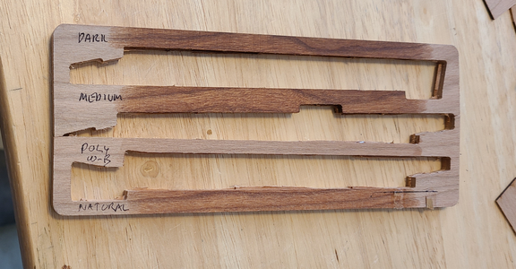
I'm probably going to put a finish on the hull interior soon. It will be difficult to get at some areas after many of the next steps are done. I'm going to use Watco Danish Oil One Step Finish this time around. I took a cherry "sprue" from the kit for a test:
1718903753306.png
The top finish labeled "Dark" is the Dark Walnut version of the Danish Oil. The finish labeled "Medium" is the Medium Walnut version. And the bottom finish labeled "Natural" is, surprise, the Natural version. The 3rd from the top labeled "Poly W-B" is Minwax Water-Based Wipe-On Poly. I used that for the most part on my Ragusian Carrack, and was never as happy with it as the Oil-Based version I used on the Bonhomme Richard cross-section, but wanted to try it to be sure I didn't want to use it here. It dries almost immediately, but IMHO does not bring out the warmth, grain and color of the other finishes, even the oil-based version of Minwax Wipe-On Poly.

My intention is to use the dark walnut version on the inside of the hull, thinking most ship innards tend to be, or turn, dark, and the lighter versions for planking, details, etc. There isn't a huge difference between them, but a subtle one that I hope will look good. I will also be using some colors like black and red, probably inks, at some stage, but we'll have to see.

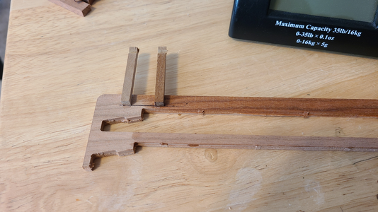
Once concern is glue adhesion with a product with the name "oil" in it. But Watco Danish Oil not all oil, but a blend of oil, vanish and additives, and is about 2/3 mineral spirts, meaning it sinks into the wood rather than making a "coating" and at least the first coat dries quite fast. But to test glue adhesion, I took some scraps of walnut, dipped one in the Danish Oil, and after drying, glued one finished and one unfinished to the above sample:

1718904865538.png

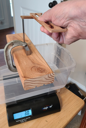
I used Ponal Express glue, took care to apply the same amount of glue and glued surface, and allowed to dry overnight. I glued notches to facilitate application of force to improve the accuracy. My test setup used a digital scale I have:
1718904969409.png
Due to the small glued surface, and the method of application of force, the failure force was not great. And unfortunately, this scale does not have a maximum weight feature, so I had to apply the force gradually, watching the indicated weight. To keep the test sample parallel and hold it better, I actually grabbed and held it in adjustable pliers.

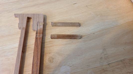
The results:
1718905120430.png
My test indicated a force of about 3 pounds 4 ounces (1.48kg) for the surfaces with Danish Oil, and 3 pounds 6 ounces (1.53kg) or so for the untreated wood. (Sorry, I'm somewhat conversant in metric, but force in Newtons stymies me for some reason, and I have to use mass - kg).

That was about what I expected, based on previous tests I'd done with Test of Different Glues On Differing Surfaces. Neither test is comprehensive, but I feel good enough putting a coat of Watco Danish Oil on my kit's wood surfaces that will later have parts glued to them. Another advantage of applying finish before gluing is that surplus glue does not stain the wood or prevent it from receiving stain or finish afterwards.
 
I like your choice of WATCO. I used it exclusively for my scratch build of Serapis. See attached for how I used all three of the WATCO Walnuts (light, medium, dark) plus the natural to "color" the model. Decking was Natural. Beams were Light. Rails Medium. Vertical balusters, seats of ease and other decorative trim were Dark Walnut. The wood was alder for everything, except carvings, which were pear. I love the way it highlights the grain and adds depth/warmth to the wood...just as it has made your Granado "Come ALIVE"!!
bow.jpg
 
I like your choice of WATCO. I used it exclusively for my scratch build of Serapis. See attached for how I used all three of the WATCO Walnuts (light, medium, dark) plus the natural to "color" the model. Decking was Natural. Beams were Light. Rails Medium. Vertical balusters, seats of ease and other decorative trim were Dark Walnut. The wood was alder for everything, except carvings, which were pear. I love the way it highlights the grain and adds depth/warmth to the wood...just as it has made your Granado "Come ALIVE"!!
View attachment 455190
Thank you, I think it will work well for me. As I said, I used it on my pearwood BH and was pleased. While working on other models, I tired of cleaning my brush after treating small, separate pieces, and tried a water-based finish. Even though on walnut, I was not pleased with it. So back to Watco for this one. So far, so good.
 
Looking on yours and @Keef s model, I have the feeling that your models are earlier completed than mine - you are both on very good ways
Bravo
 
Looking on yours and @Keef s model, I have the feeling that your models are earlier completed than mine - you are both on very good ways
Bravo
Well, as I'm not doing all the iron and copper bolts, or treenailing, it will go much faster. Less quality, but I've attempted some treenailing, and it did not go well. So....
 
I think your dark color for interior is good, where no sun shines to lighted the wood, and on upper surfaces like planks and other deck items the lighter would be correct to show a bit of sun bleaching of the wood.
 
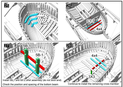
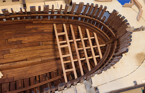
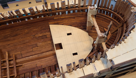
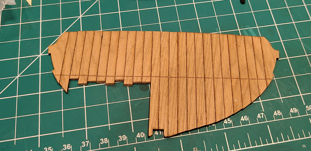
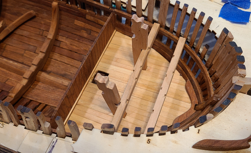
The lower deck structure at the bow is positioned using templates C1-7, which attach to main Template #1. That didn't work for me.
1719337242155.png
The C1-7 templates did not fit properly into the shape of the inner hull at that point. I also didn't like making that entire beam & floor structure based on the level and inclination of only 2 beams 6A-2, trying to keep the whole thing level, or at whatever angle it was intended to be.
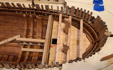
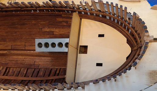
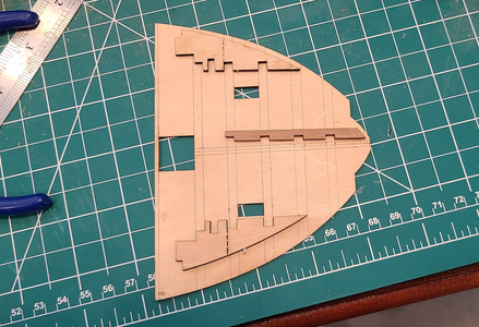
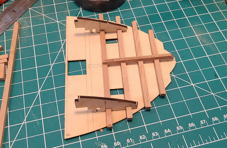
Instead, I took the planking template used for this space, placed it where I felt it should be (and where it fit), and placed the bulkhead templates behind it:
1719337483872.png
There is a line engraved on one side of the bulkhead templates, and as that lined up very accurately with the deck template, I decided to make that the location of the deck area.
I used the templates and other pieces that go in this area to mark the location of the beams on the deck template:
1719337614298.png
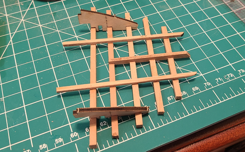
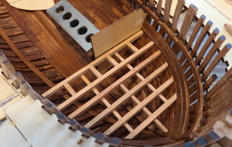
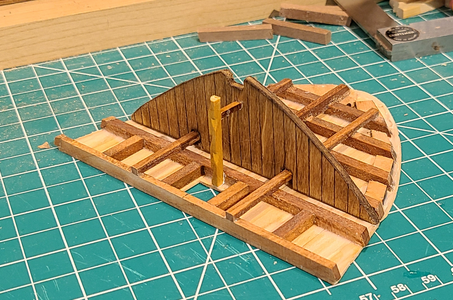
Then glued the main pieces for the deck support to each other:
1719337736434.png
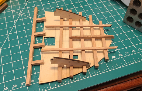
Since there is no connection between the above 4 cross beams and the next two, I added stringers along the bottom to make everything into one assembly:
1719337831650.png
and added some additional connections from the sternmost beam to its neighbor:
1719337949859.png
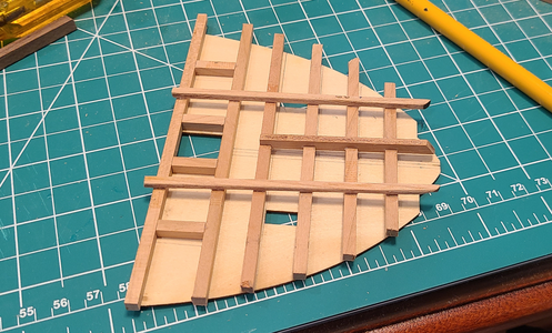
giving me an assembly that could stand on its own for positioning:
1719337991729.png

After a bit of sanding, I had a pretty good fit:
1719338047761.png
and it seemed to be the correct height, based on the bulkhead template:
1719338082451.png

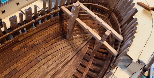
Since I hadn't used the correct template to locate the beams within the bow, and therefore had not used the windlass structure to confirm it, I had to be sure that the windlass structure fit, and that the fore-to-aft location matched up:
1719338226491.png
I taped pieces of scrap to the windlass supports to help determine if they were vertical (at the fore edge, as the back edge is tapered):
1719338317211.png
This helped me locate the proper hole locations in the deck and properly shape the bottom of the supports:
1719338391695.png
1719338428545.png

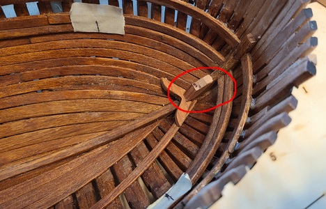
I wanted a more secure support for the leading edge of the deck, so added the small piece circled below:
1719338485217.png
This helps locate the deck and also makes it more secure.

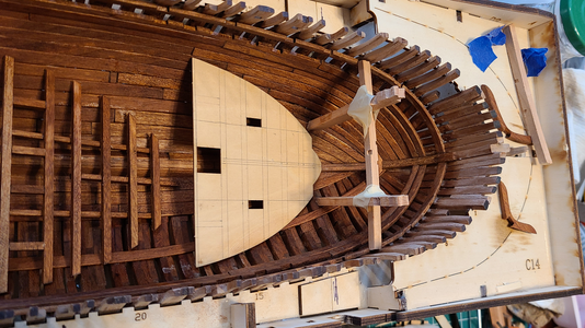
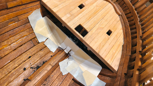
In the meantime, I had installed the decking on this area. I used the included 1.5x5 strips, rather than the laser-cut pieces, because they're easier to use: No sanding of the char, and only need be cut to length, and sanded in bulk after positioning.

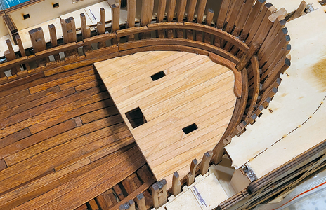
Oh, while I had intended to keep half of this (and all) decks open to show the structure, the structure of this deck was nothing special (especially with my modifications), and there was nothing to see below it. So I decided to keep this decking complete, and possibly show details on it along with the rooms, through open framework above it.

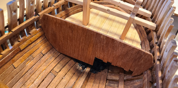
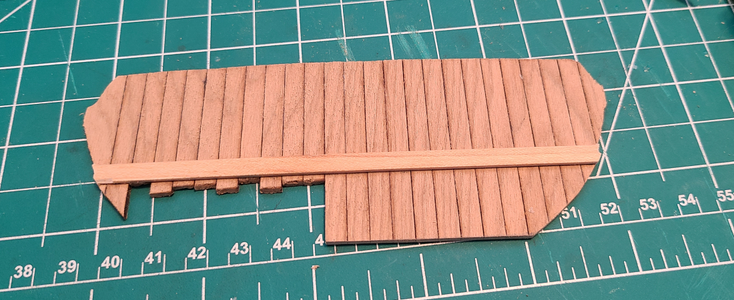
I also wanted the center of the deck structure better supported than just by its sides. So I took a piece of template plywood to make the bulkhead shown on Goodwin's drawings between the coal hole and the void space. The kit included only a single support, which would be difficult for me to mount considering my assembly procedure, and the bulkhead is more accurate. I didn't spend much time on it, inking on the plank lines and a quick coat of stain, as I doubted it would be visible.
1719338861774.png
As per Uwe's build, I also did not include the ladder to the coal hole. The hole seems small for a ladder, the ladder would interfere with the coal, and a person standing in the coal hole could reach the deck above to place coal on it. I also added some (hopefully invisible) reinforcement around the deck to increase the strength of the assembly.

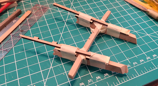
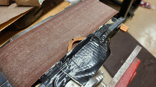
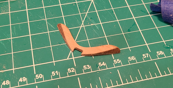
The center bow reinforcement is intended to go through this deck, at an angle, which really complicates the outline of the deck and shaping of planks. So I took the easy way out, and tapered this reinforcement to have only the portion shown above the deck left. Since it is a small piece and hard to hold when sanding, I rigged a way of holding and pivoting the piece while sanding with my belt sander:
1719339157526.png
Crude, but it worked.
1719339124282.png
I would have preferred the fore portion to be a bit thinner, but it was ready to fall apart as it was.

After the support was installed, it does look like it penetrates the deck, I think:
1719339266445.png
Here is a view showing the bulkhead underneath, separating the coal hole from the void space, as well as providing support for the deck:
1719339337595.png
As expected, the bulkhead is not very visible, so deserved no more time to make it look better.

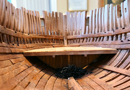
I kind of wanted to add coal to the coal hole, and knew that now was the time to do that if I wanted. So I made a "dam" out of cardstock, with wax paper added to the inside to prevent sticking, then added some scale coal that I had, coating it completely with think CA glue:
1719339477188.png
After the glue dried, I removed the "dam", and we have a mound of coal in the coal hole:
1719339520891.png
Yes, the coal is in too large of chunks, but I don't think this will be very visible in the end, so it probably won't matter. If anything, I think I will be able to see only the glint of the coal, so this should be okay.

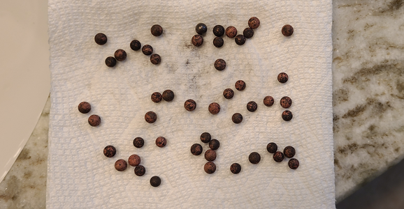
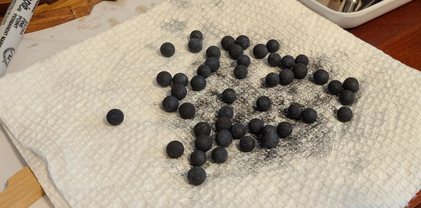
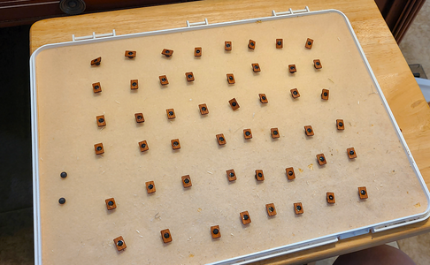
While it really should be grouped later with other structures, I took pics of blackening the 50 brass cannon balls included with the kit. I first use JAX Pewter Black, which I had more of, and the result was not good:
1719339700618.png
I have had mixed luck with this blackener. I then soaked the balls in acetone and tried again with Birchwood Casey Brass Black, with better results:
1719339788686.png
Each of these gets placed on a hole in a shelf in the mortar magazine. I've done some pretty sloppy work in gluing balls into holes, as the excess glue oftentimes shows up. I tried a different method here, placing the pre-stained shelves atop the balls, and glueing from the bottom with gel CA:
1719339900529.png
This worked reasonably well. I can now install each shelf with ball already in place when I make the mortar magazine assembly.

Until next time, thanks for all the likes and comments, I really do appreciate it!
 
Back
Top