
Bravo - very good progress with the frame-production
-> in some time you will be already able to install them
-> in some time you will be already able to install them

 |
As a way to introduce our brass coins to the community, we will raffle off a free coin during the month of August. Follow link ABOVE for instructions for entering. |
|
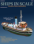 |
The beloved Ships in Scale Magazine is back and charting a new course for 2026! Discover new skills, new techniques, and new inspirations in every issue. NOTE THAT OUR FIRST ISSUE WILL BE JAN/FEB 2026 |
|
Good luck with thatFinally, I hand sand the inside profiles up to 180 grit sandpaper, giving a reasonably smooth finish, which I hope to not have to alter.
 .
.Thanks, Allan. Yes, I have Goodwin's book and have been searching for information elsewhere as well, mostly for ideas, detailing, etc. I don't think I'm familiar with the Wiki Commons site, though.Looks like a great build! I am duly impressed that they detail the taper of the knee of the head which is not always addressed. Are you by chance using the Peter Goodwin AOTS book on Granado or any of the high resolution drawings of bomb vessels on the Wiki Commons site as a reference as well? Those on Wiki are some years later than Granado so might not so useful.
Allan
Thank you. Yes, I will shortly be adding to the dock, making sure I can fit in the various components.Bravo - very good progress with the frame-production
-> in some time you will be already able to install them
I guess Allan is refering to this site, which I explained in detail in this topic:Thanks, Allan. Yes, I have Goodwin's book and have been searching for information elsewhere as well, mostly for ideas, detailing, etc. I don't think I'm familiar with the Wiki Commons site, though.


 It would have been nice to note in the instructions to NOT glue these pieces at this time.
There are 12 bomb vessels on the website, with a total of 47 high res plans. There are only one or two plans for a few and as many as 7 to 9 for others They cover a wide range of years so may not be applicable for Granado but you still may find them interesting. There are 3000 drawings on the site. about 800 of which are high resolution. The list is alphabetical but it goes for a couple pages then starts again for some reason so a bit time consuming if you do not know the name of the ships you want to see. In this case the ones I found in high res areI don't think I'm familiar with the Wiki Commons site, though.
CROSS SECTIONS RMG_J0393.png")
_CROSS SECTION WITH PLANKING DETAILS RMG_J1425.png")
There are a number of cross section plans I found really interesting such as the two below. Notice the double outboard planking and deck planking in the second drawing. The vessel is Fury 1814 but the drawing is from later so I don't know if that was a later innovation or had been done earlier.

ja Ja - I told you not to glue to early - and there is no need to use a lot of glue - and if glue use waterbased one - you can easily reopen when necessaryWell, darn. I started to make the remainder of the dock, and now see that the end pieces A & B supporting the stem and stern should not have been glued in place. I made sure they were nice and strongly glued, to shape each end of the keel properly. I left the ends loose, but not the keel supports, following this instruction:
View attachment 449066
But I now see that the horizontal template pieces cannot be fitted in place once they are assembled.
View attachment 449067
And I wouldn't trust making them in the final position, so I guess I take the above pieces A and B, so securely and accurately glued in place, out.
Rats!
View attachment 449068
 wasn't inserted when spelling the word normally), on to fixing my problem. As mentioned above, I had glued parts A and B that support and locate the stem and stern portions of the keel, without any other parts being attached, which made it impossible to continue with the dock assembly. So, I soaked the Ponal glue used to soften it and remove the parts. The stern Part B came off fairly easily, with some mallet tapping and prying:


No, I used white glue, and not TOO much of it, but will probably break it apart using pliers or something when it comes to that. It's so sturdy, I thought about not using glue at all, but had heard it should be glued, so....If you glued it together with PVA you can always disolve the glue with Acetone.
White glue is PVA, so put some Acetone on it with a cotton tip and the glue joints can be easily separated.No, I used white glue, and not TOO much of it, but will probably break it apart using pliers or something when it comes to that. It's so sturdy, I thought about not using glue at all, but had heard it should be glued, so....
I don't think it will be a big problem. I certainly won't let the hull be harmed.

Ah, yes, I knew that, right? I've used water to separate PVA/White glue joints, and it works pretty well (thankfully). Does acetone work better?White glue is PVA, so put some Acetone on it with a cotton tip and the glue joints can be easily separated.
I use watertight PVA so I don't have another option than AcetoneAh, yes, I knew that, right? I've used water to separate PVA/White glue joints, and it works pretty well (thankfully). Does acetone work better?
.

